User Manual DEV 1953
Copyright DEV Systemtechnik GmbH 2015-2017 27
3.3 Product Drawings
The front side of the DEV 1953 is identical for all product configurations. Just if the
product was ordered with Option 14, different power supply modules are installed.
The rear side of the DEV 1953 differs with respect to the installed module types and
quantities. Thus, only three drawings of the rear side are provided, other product
configurations can be easily derived.
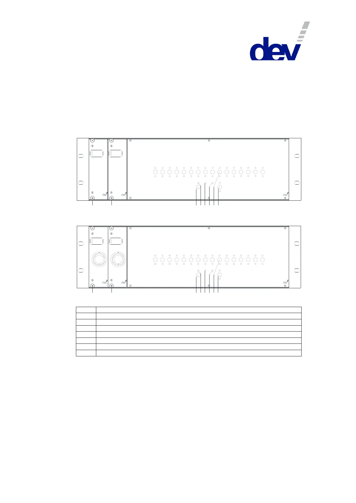
3.3.1 Front Side DEV 1953
Front View (AC/DC Power Supplies, standard):
1 2
Power Supply
Opera tion
Failu re
12 -00 22
Power Supply
Opera tion
Failu re
12 -00 22
3
1 2 4
5 6
7
8 9 10
11 12
13
14
15 16
Sim ultaneous
Rem ote
Indiv idu al
Loc al Auto
In A
In B
Univers al Switch C hassis
DEV 1 953
3
4 5
6
7
8
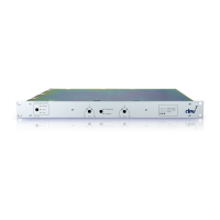
Front View (DC/DC Power Supplies, Option 14):
1 2
Power Supply
Opera tion
Failu re
12 -00 15
Power Supply
Opera tion
Failu re
12 -00 15
3
1 2 4
5 6
7
8 9 10
11 12
13
14
15 16
Sim ultaneous
Rem ote
Indiv idu al
Loc al Auto
In A
In B
Univers al Switch C hassis
DEV 1 953
3
4 5
6
7
8
Yellow LED indicating "Remote" Mode
Yellow LED indicating "Local" Mode
Yellow LED indicating "Auto" Mode
Channel push buttons "1"…"16" with green LEDs indicating "In A" or "In B"
Switching mode push button and yellow LEDs "Simultaneous" & "Individual"