User Manual DEV 1953
136 Copyright DEV Systemtechnik GmbH 2015-2017
7 Connectors
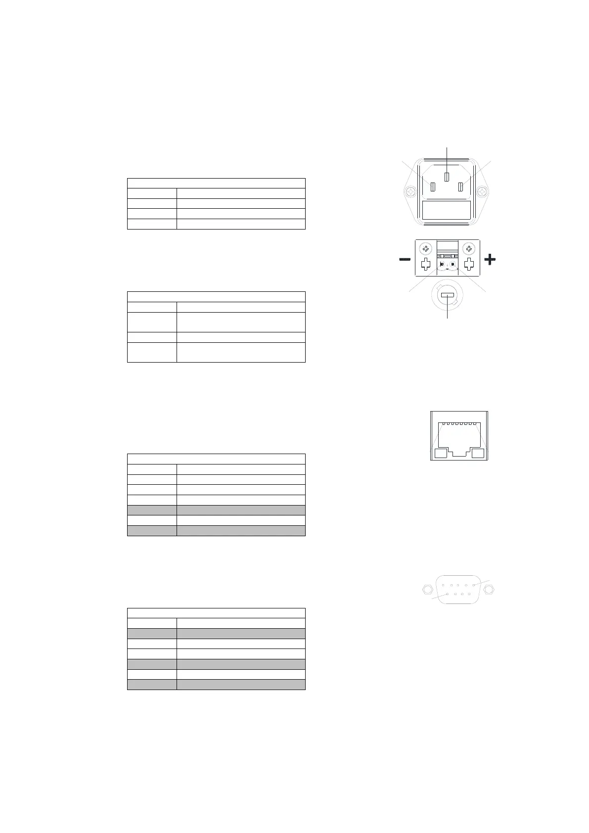
AC Power Plug
Connector: IEC rubber connector (male) IEC 60320 C14
Connector screws: none
DC Power Plug (Option 14)
Connector: Phoenix Contact Feed-through Header,
Type DFK-MSTB 2,5/ 2-G-5,08 - 0707248
Connector screws: none
Pin for positive DC potential
(+36...+75 V DC)
Pin for negative DC potential
Fuse holder containing glass fuse
size 5*20 mm, value 4 A T
• The matching connector is part of the delivery
(Phoenix Contact Printed-circuit Board Connector, Type MSTB 2,5/ 2-ST-5,08 – 1757019, DEV 79-0303)
• Alternatively, the device can be powered with a negative voltage (-36...-75 V DC) by inverting the polarity.
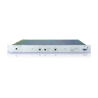
Ethernet Connector (at the CPU module)
Connector: RJ-45
Connector assembly: none
• "do not use" means that normally the pin should be left open.
Serial Connector (at the CPU module)
Connector: Sub-D 9 (female)
Connector screws: UNC 4-40
Serial Connector (RS 232)
• "do not use" means that normally the pin should be left open. It is usually not a problem to use a fully
populated 1:1 Sub-D 9 (m)-(f) cable to establish a RS 232 connection between the device and a PC.