User Manual DEV 1953
30 Copyright DEV Systemtechnik GmbH 2015-2017
1
5
7
4
6
1
8
6
4
7
5
3
2
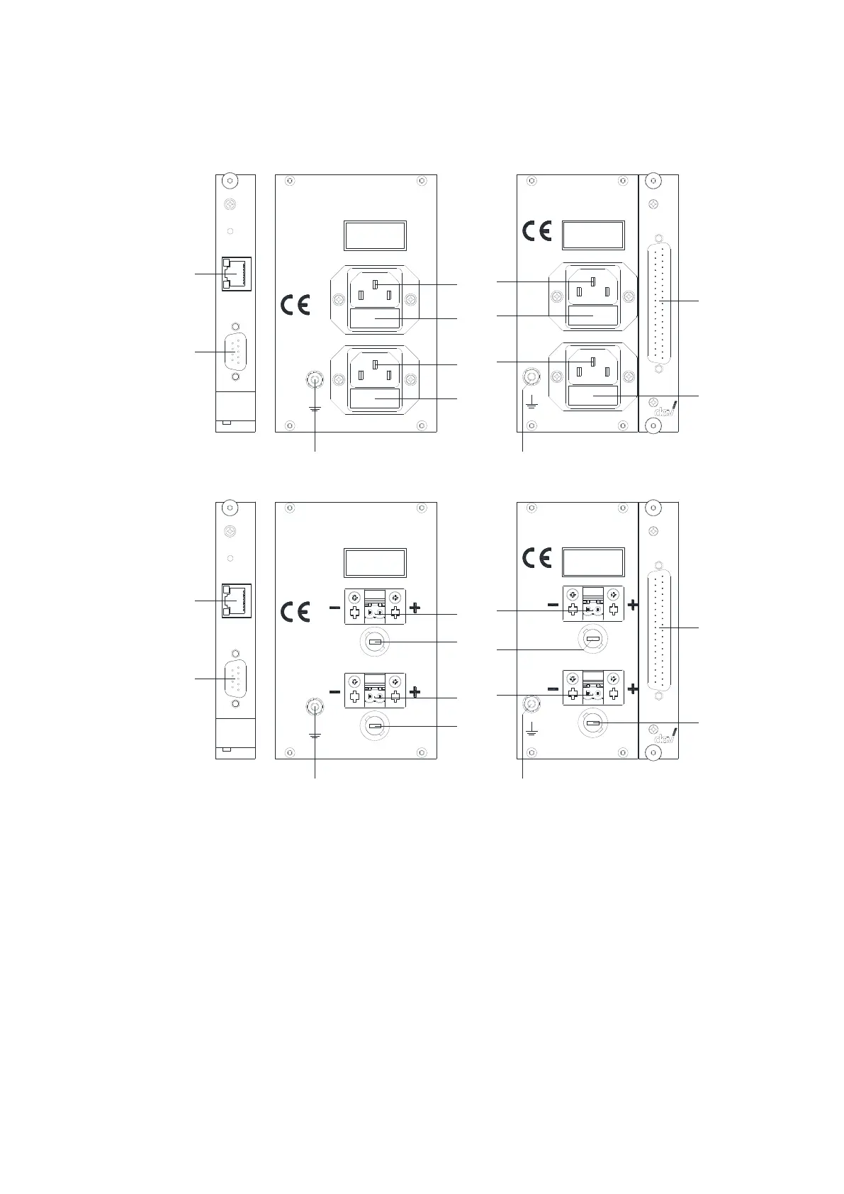
Standard
plus Option 56 (or 57)
Com
Ethernet
Reset
100...240 V
Disconnect pow er
W ARNING:
before opening!
50...60 H z
50 VA
Supply 1 - Fuse 2 A T
Supply 2 - Fuse 2 A T
100...240 V
Disconnect power
W ARNING:
before opening!
50...60 H z
50 VA
Supply 2 - Fuse 2 A T
Supply 1 - Fuse 2 A T
M&C 1
1
5
7
4
6
1
8
6
4
7
5
3
2
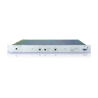
Option 14
plus Option 56 (or 57)
Com
Ethernet
Reset
Supply 1 - Fuse 4 A T
-36... -72 V D C or
Disconnect pow er
W ARNING:
before opening!
+36...+72 V D C
100 W
Supply 2 - Fuse 4 A T
Disconnect power
W ARNING:
before opening!
M&C 1
Supply 1 - Fuse 4 A T
Supply 2 - Fuse 4 A T
-36... -7 2 V D C or
+36...+72 V D C
100 W
Next, establish the external Ethernet connection by plugging an Ethernet cable
from your network to the "Ethernet" (3) of the CPU module.
If the basic network setup via serial interface is required (please refer to chapter
4.4.2.2), and/or if it is intended to control the device via the serial interface using
Sandar Prosan protocol, Leitch protocol, or QEC protocol, a serial connection
between a PC and the serial connector of the CPU module labeled "Com" (2) is to be
established. The configuration of the serial interface is described in chapter 4.4.1;
please refer to chapter 7 for the pin assignment of the serial connector.
If the device is equipped with a digital interface module (Option 56 or Option 57)
and if it is intended to control the DEV 1953 via the digital interface, connect a pre-
pared cable to (8). The pin assignment of the digital interface module connector is
stated in chapter 7.