LT-2320
16
SERVICE
CPAP SERVICING AND PARTS
REPLACEMENT
Tools and Equipment Needed:
• T-10 Torx driver
• Needle nose pliers
• Digital Multimeter for measuring AC/DC voltages and resistance
• AC power source (100 to 240 VAC 50/60 Hz)
Inspecting Internal Components
When servicing or troubleshooting the CPAP, it may be necessary to
closely inspect all of the internal components in order to determine the
cause of the problem or issue. The following steps are provided as a
guide to assist you when performing a detailed inspection or
evaluation of the CPAP.
During service, do not touch the contacts at the end of the ribbon
connector/cable. Grease or oil from your ngers will render the display
inoperative.
Inspecting components in and on the blower
chassis:
1. Remove bottom cover using instructions listed on pg. 17.
2. Inspect the bottom cover foam pieces and mounting bosses for
damage. Replace as needed.
Mounting
Bosses
Mounting
Bosses
Foam
3. Remove blower. See ‘to remove and replace blower’ section.
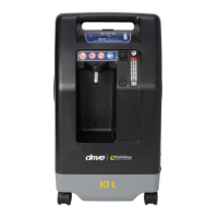
4. Inspect the blower foam pieces and the blower discharge isolator.
Ensure they are not damaged. Replace as needed.
Blower Isolator
Blower Isolation
Foam
5. Look for evidence of water residue inside the blower housing.
6. Verify that the blower halves are properly snapped together. No
visible gap should be present between the top and bottom
sections. Also inspect the chassis manifold for any damage.
Replace if necessary.
Chassis Manifold
7. Make sure the ow element is positioned properly and not dirty or
damaged.
Flow
Element
Top Blower
Foam
8. Replace blower. See ‘to remove and replace blower’ section.
Inspecting components in and on top of the
main chassis:
1. Remove top cover using instructions listed on pg. 17.
2. Remove PC board. See instructions ‘to remove and replace PC
board’ section.
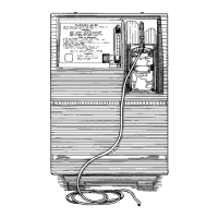
3. Inspect the LCD display mounting to the front of the chassis and
ensure that it is positioned correctly.
Ribbon
Connectors
LCD Display
& Mount
Isolator
4. Closely inspect both ribbon connectors. Make sure there are no
breaks or nicks in the wire insulation. Also be sure the smaller
ribbon connector is securely attached to the Encoder PC board.
NOTE: During service, do not touch the contacts at the end of
the ribbon connector/cable. Grease or oil from your ngers will
render the display inoperative.
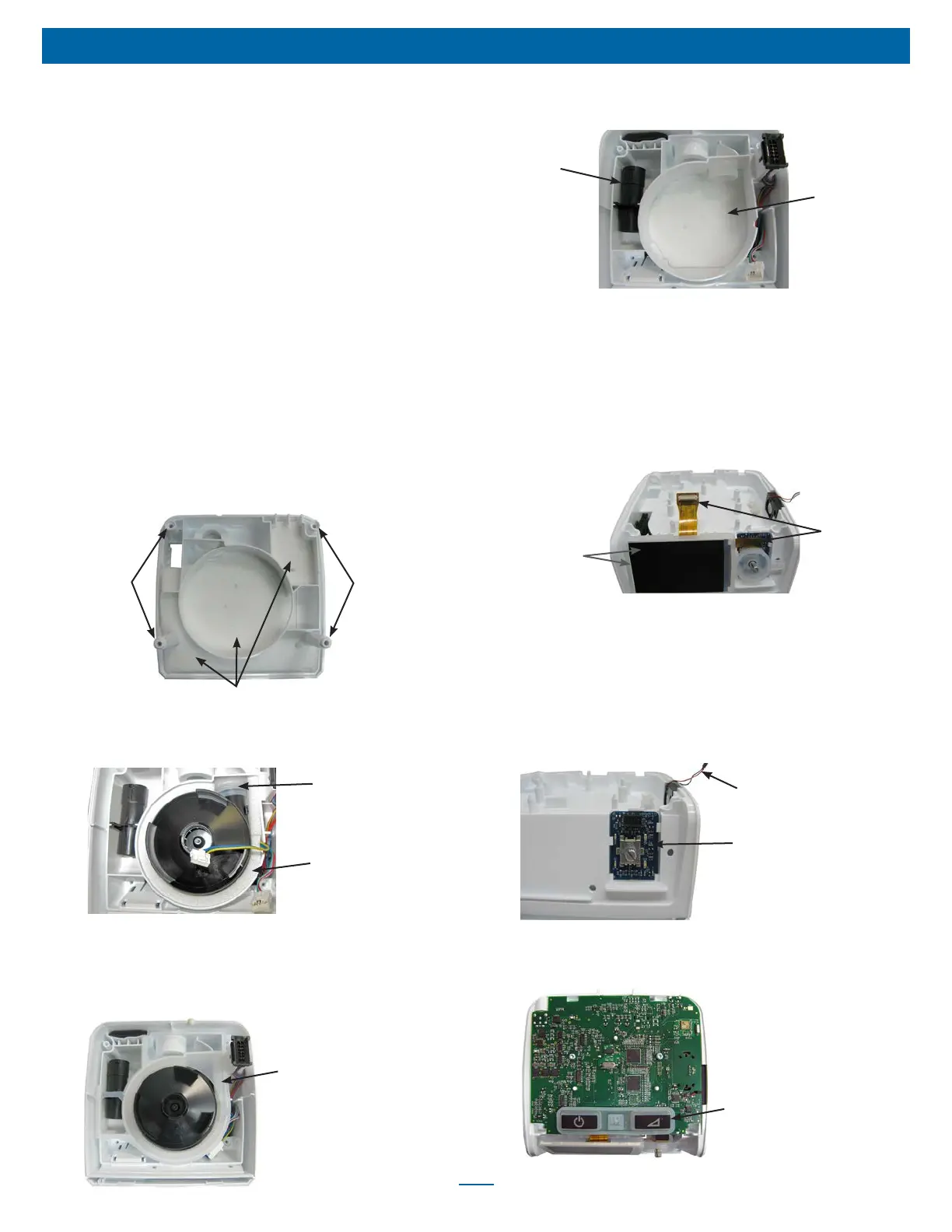
5. Inspect the Encoder PC board for any broken connections
around the stem that the rotary knob plugs onto.
Speaker Wires
Encoder PC Board
6. Inspect the speaker for any broken wires.
7. Remove the keypad from the PC board by gently pulling upward
until the ‘rat tails’ are out of the holes.
Keypad