LT-2320
19
SERVICE
7. Type 'Sn=nnnnnnnnnn' where nnnnnnnnnn is the 10 digit serial
number read in the previous step.
8. Read the hour meter("Uh<cr>)-a new PC Board should have
000000000.0 hours. It is recommended that the original hour
meter value be restored if the original blower is used. Set the
hour meter by typing 'Uh=nnnn<cr>' where nnnn is the hour
meter reading X10 (Ex: 100.5 hours would be set by typing
'Uh=1005<cr>').
9. Read the Compliance Meter ("Up<cr>")-a new PC board should
have 000000000.0. Clear the Compliance Meter if it is not by
typing 'Up=c<cr>'. The CPAP will return 0000000000.0.
NOTE: SmartCode data will also clear at this time.
10. Check the hardware and rmware version information. Read and
record the following:
a. BIOS rev "VB<cr>"
b. Firmware rev "VF<cr>"
Check the present version of rmware to make sure the board is
up to date. Install new rmware if the board has an old revision.
11. Clear the error code by typing 'Ec<cr>' the PAP will return "OK".
12. Clear the fault log by typing 'Uf=c<cr>'the PAP will return "OK".
13. Set all device settings to their default by typing 'TD<cr>. The PAP
should return "OK".
14. Recalibrate the unit using the Manual Calibration Procedure.
15. After the calibration is complete, close Hyper Terminal and set the
clock. This requires the use of the DeVilbiss Remote Control
Program which is included in SmartLink Desktop Software
version 3.0 or higher. If necessary, install the software at this
time.
16. Connect the PAP to a PC Serial Port with cable DV63D-615. In
order to set the clock, open the DeVilbiss SmartLink Desktop
Software and click on the Remote Control Program. When the
program nds the PAP, click on the clock settings tab. Then click
on the clock in the middle of the screen. When you click this, a
message box will let you know that, by clicking this, all data will
be permanently removed and will ask you if you want to proceed.
By clicking "OK" the clock will be set to your computer time, and
all data will be erased.
17. Close the software and disconnect the unit from the PC.
To Remove and Replace LCD Display, Encoder
PC Board, or Manifolds for Pressure and Flow
Transducers
1. Remove PC Board using instructions listed previously and set
aside PC Board with Keypad attached in a safe, clean location.
2. Use a ngernail to gently pry the LCD Display ribbon connector
from Encoder PC board connection.
Disconnect Display Ribbon
Connector from Encoder PC Board
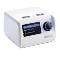
3. Remove the Display and its silicone display mount isolator.
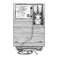
4. If replacing Encoder PC board, release from the chassis by
carefully pushing on the top latch while lifting the rotary knob
stem up until the board is released. Install new Encoder board by
positioning the board so that the Display’s connector is on top,
aligning the board in the chassis guides and pushing into
position. The top latch will click into place.
Push Latch to Remove
Encoder PC Board
5. If replacing the Display, remove old Display from the silicone
mount isolator and carefully insert new Display ensuring that
neither ribbon connector is bent or damaged in the process.
Silicone Mount Isolator
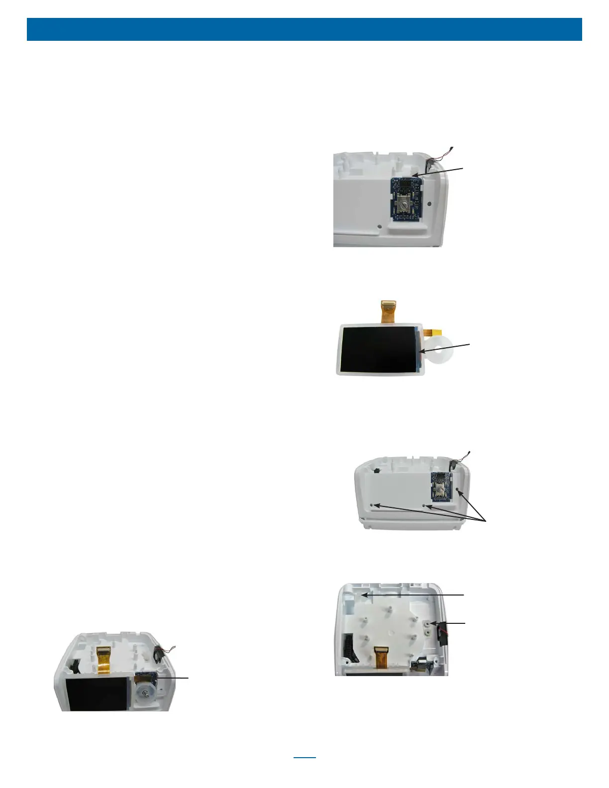
a. Position the isolator so that the back two plugs align with the
holes in the Display cavity, and the Rotary Knob isolator plug
aligns with the hole to the right of the knob stem. Push the
three plugs into their corresponding holes to attach the
isolator to the main chassis.
Holes for Isolator Plugs X3
b. Attach ribbon connector to the Encoder PC board.
6. If replacing manifolds, pull appropriate silicone manifold from
main chassis.
Pressure Sensor Manifold
Flow Sensor Manifold
a. If replacing the manifold for the pressure sensor, press tall
connector over the larger port in the chassis.