LT-2320
18
SERVICE
To Remove and Replace PC Board / Keypad
1. Remove top cover using instructions listed previously.
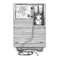
2. Remove two short T-10 screws from PC board.
Speaker Wire
Connector
PC Board
Screws
3. Carefully remove speaker wire connector from top of PC board
by lifting upwards.
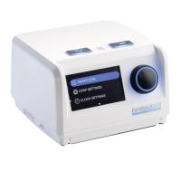
4. Carefully lift front of PC Board to gain access to the LCD
display’s ribbon connector. Ensuring that the ribbon connector is
not bent in the process, disconnect the display connector from
the PC board.
Display Ribbon
Connector
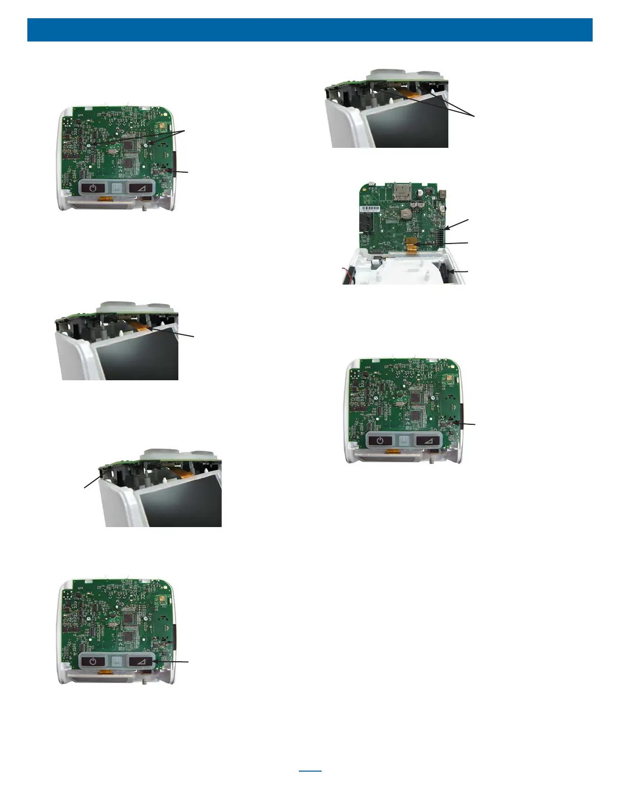
5. Lift PC board out of the main chassis until the main wire harness
connector is accessible.
6. Release main wire harness connector latch and carefully pull
board from connector.
Wire Harness
Connector
7. Remove board from top of chassis.
8. Remove keypad from PC board by carefully pulling upward until
the “rat tails” are out of the holes.
Keypad
9. Position the keypad so that the Ramp key is on the front right of
the new PC Board. Pull the “rat tails” through the corresponding
holes in the new board using needle nose pliers. Ensure that the
“rat tails” are pulled completely through the board with the
keypad ush with the top of the board.
Rat Tails
X4
10. Align the LCD display ribbon connector with the PC board’s
connector and push into place without damaging the ribbon.
PC Board
Connector
Attach Display
Ribbon Connector
Wire Harness
Connector
11. Hold main wire harness connector with both forengers or needle
nose pliers and align with PC board’s connector. Then carefully
push until it snaps into place.
12. Reconnect speaker wire connector to PC board by pushing
straight down (red wire closest to delay button).
Speaker Wire
Connector
13. Ensure PC board is properly positioned on chassis and secure
with two T-10 screws.
14. Replace top cover using instructions listed previously.
NOTE: If a NEW PC board was installed, proceed with the
following steps including recalibration.
The following steps including recalibration are required when
installing a new PC board:
1. Connect the PAP to a PC Serial Port with cable DV63D-615 and
turn the PAP on.
2. Use a terminal program (such as Windows Hyper Terminal or
equivalent) with COM Settings 9600 baud, no parity, 1 stop bit,
Flow Control set to none.
3. When the unit is connected, Type 'Mn<cr>. The PAP will report
the model number saved in memory. It should be "00000" if the
PC Board is new.
4. Read the Model number from the PAP label in the back of the
unit (EX; DV64D)
5. Type 'Mn=nnnnn where nnnnn is the 5 digit model number read
in the previous step. The PAP should return the 5 digit model
Number.
6. Read the Serial Number from the label located on the back of
the unit.