About the module Module pinout
ConnectCore for i.MX51 Hardware Reference Manual
29
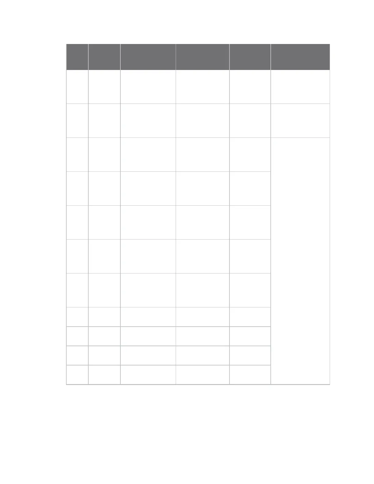
Pin Type Signal name Use on module
Use on
development
board
Comments
J2:12 GPIO27 DISP1_DAT11 i.MX51: DISP1_
DAT11
HDMI, VGA
and LCD1
Data, Boot
Configuration
J2:13 GPIO27 DISP1_DAT12 i.MX51: DISP1_
DAT12
HDMI, VGA
and LCD1
Data, Boot
Configuration
J2:14 GPIO27 DISP1_DAT13 i.MX51: DISP1_
DAT13
HDMI, VGA
and LCD1
Data, Boot
Configuration
On the Development
Kit, DISP1 and DISP2
are configured at 18-
bit, and connected
to 24-bit LCDs.
On the Development
Kit, some DISP1
signals are used to
configure the boot
process.
On the Early
Availability Kit,
DISP1 and DISP2 are
configured at 24-bit,
and connected to
24-bit LCDs.
J2:15 GPIO27 DISP1_DAT14 i.MX51: DISP1_
DAT14
HDMI, VGA
and LCD1
Data, Boot
Configuration
J2:16 GPIO27 DISP1_DAT15 i.MX51: DISP1_
DAT15
HDMI, VGA
and LCD1
Data, Boot
Configuration
J2:17 GPIO27 DISP1_DAT16 i.MX51: DISP1_
DAT16
HDMI, VGA
and LCD1
Data, Boot
Configuration
J2:18 GPIO27 DISP1_DAT17 i.MX51: DISP1_
DAT17
HDMI, VGA
and LCD1
Data, Boot
Configuration
J2:19 GPIO27 DISP1_DAT18 i.MX51: DISP1_
DAT18
Not used
J2:20 GPIO27 DISP1_DAT19 i.MX51: DISP1_
DAT19
Not used
J2:21 GPIO27 DISP1_DAT20 i.MX51: DISP1_
DAT20
Boot
Configuration
J2:22 GPIO27 DISP1_DAT21 i.MX51: DISP1_
DAT21
Boot
Configuration