D-Control Guide52
Channel Strip Mode Controls
Each channel strip has a set of Channel Strip Mode controls
for displaying and editing pan, plug-in, mic pre, insert, or
send parameters on the encoder section of the D-Control
channel strip.
Page Up and Page Down Switches
Control parameters are arranged on channel strip rotary en-
coders in pages, or groups of up to six parameters at a time.
The Page Up and Page Down switches light to indicate the
presence of additional pages of sends, pan, plug-in, mic pre
parameters, or (for VCA Master tracks) slave tracks, in the cor-
responding direction on each channel strip. If no additional
pages are available, neither switch is lit.
To move the page display of parameters on the encoders up or
down:
Press a lit Page Up or Page Down switch.
Dynamics and EQ Switches
The Dynamics and EQ switches light to indicate the presence
of the corresponding type of plug-in on a channel strip.
To display a channel strip’s first Dynamics or EQ plug-in on the
rotary encoders for editing:
Press a lit Dynamics or EQ switch.
To cycle through all the Dynamics or EQ plug-ins on a channel:
Repeatedly press the corresponding switch.
Input Switch
With Audio and Auxiliary Input tracks, the Input switch is
used to put channels into Inline mode. See “Inline Console
Mode” on page 135.
With Instrument tracks, the Input switch is used to display
that track’s MIDI controls on the rotary encoders. See “MIDI
Controls on Instrument Tracks” on page 51.
Mic Pre Switch
When you press the Mic Pre switch, the controls for an avail-
able remote-controlled microphone preamplifier (such as the
Digidesign PRE) are displayed on the channel strip’s rotary en-
coders for editing. Microphone preamplifiers are declared in
the Pro Tools Peripherals dialog, and assigned to channels in
the Pro Tools I/O Setup dialog.
Inserts Switch
When you press the Inserts switch on a channel strip, plug-in
names are shown in two groups of five (Inserts A–E or Inserts
F–J) on the encoder displays.
You can use Flip mode to transfer controls for any insert (A–J)
from the channel encoders to the Faders. See “Flip Mode” on
page 133.
To toggle display of Inserts A–E and F–J on a channel strip:
1 Press the Inserts switch in the Channel Strip Mode controls
section of the channel strip to show the top level Insert dis-
play.
2 Press the Page Up and Page Down switches to toggle the top
level Send display between the two sets of five sends (A–E and
F–J).
To view the parameters for an individual plug-in:
Press the Select switch on the corresponding encoder.
To return to the top level display of plug-ins on the channel strip:
Press the Inserts switch again.
The Inserts switch flashes when a plug-in on that channel has
clipped. To clear a clip, press the Clear Clip switch in the Ses-
sion Management section. See “Clear Clip Switch and Plug-in
Clip Indicator” on page 102 for more information.
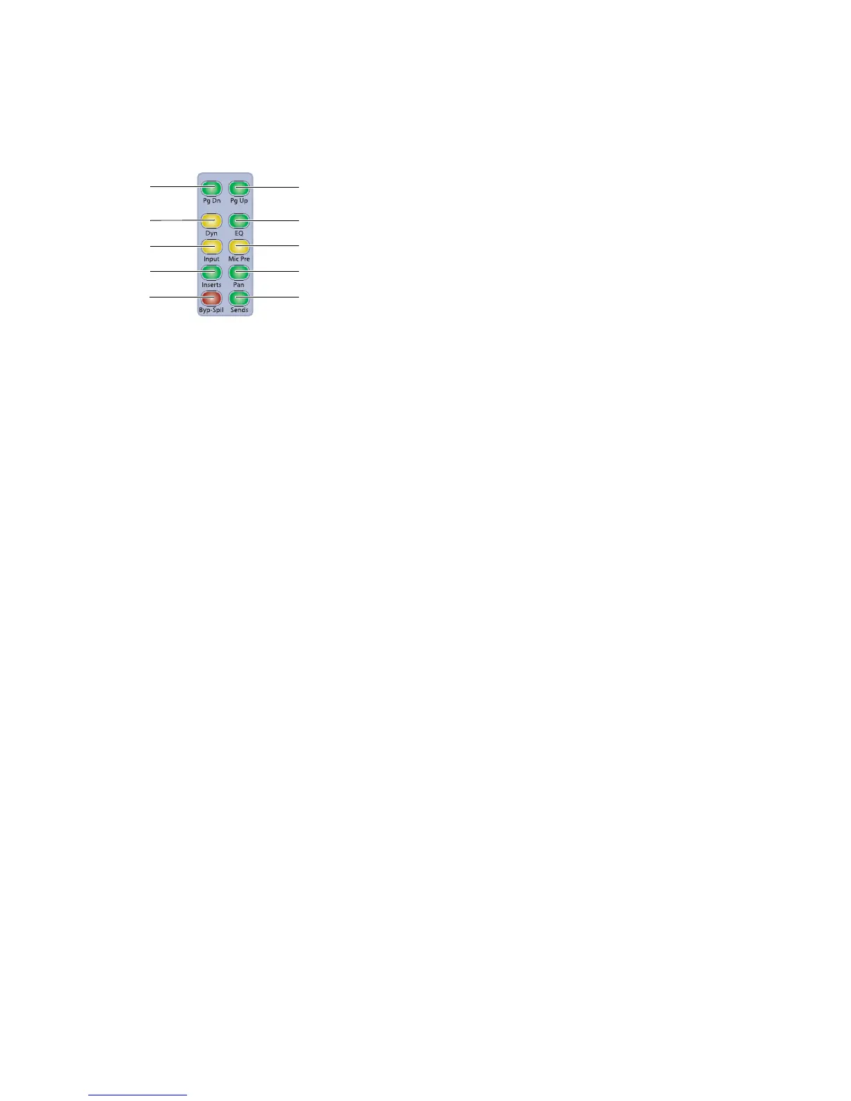
Channel Strip Mode controls
Page Up switch
Dynamics switch
Microphone
Preamplifier switch
Inserts switch Pan switch
Bypass/Spill
switch
Sends switch
Input switch
EQ switch
Page Down switch