MAINTENANCE AND FAULT FINDING
L025317 Issue 1 March 2011 5-21
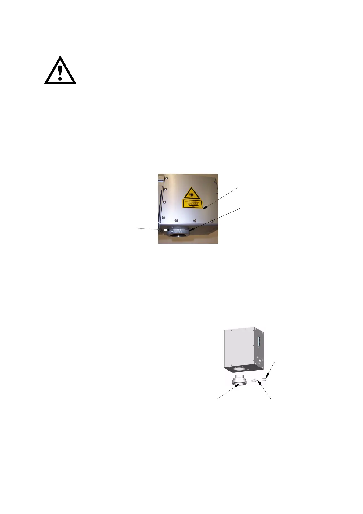
REPLACING THE LENS
WARNINGS: (1) Before undertaking any work on the laser
marking system, remove the mains power plug.
(2) This procedure is to be performed by fully
trained engineers only.
(3) The lens must not come in contact with
unprotected skin (health hazard).
CAUTION: Protect the lens from damage by shock or scratching.
The lens consists of the optics retainer and the focusing lens, which has been
adjusted at manufacture, and a connection for the compressed air hose when
fitted.
Notes: (1) Ensure the replacement lens is available before starting this procedure.
(2) In addition to its primary optical purpose, the objective, with its built-in
lens, simultaneously acts as protection from dust and alike for the beam
scanning unit. As a result, the lens should not be removed for any longer
than necessary.
(1) If a compressed air hose is present:
(i) Unscrew the sleeve nut.
(ii) Pull off the hose.
(iii) Screw out the connecting
collar.
(iv) Unscrew the lens from the
scanner head.
(v) Screw the new lens hand-
tight up to the stop into
the scanner head.
(2) To fit the compressed air hose:
(i) Screw in the connecting collar.
(ii) Slip on the hose.
(iii) Screw on the sleeve nut.
Compressed
Air
Connection
Lens
Scanner
Heads
Hose
Sleeve Nut
Connecting Collar
Lens
 Loading...