MAINTENANCE AND FAULT FINDING
5-24 L025317 Issue 1 March 2011
STATUS LEDS
Inside the controller, some LEDs display the status of the electronics.
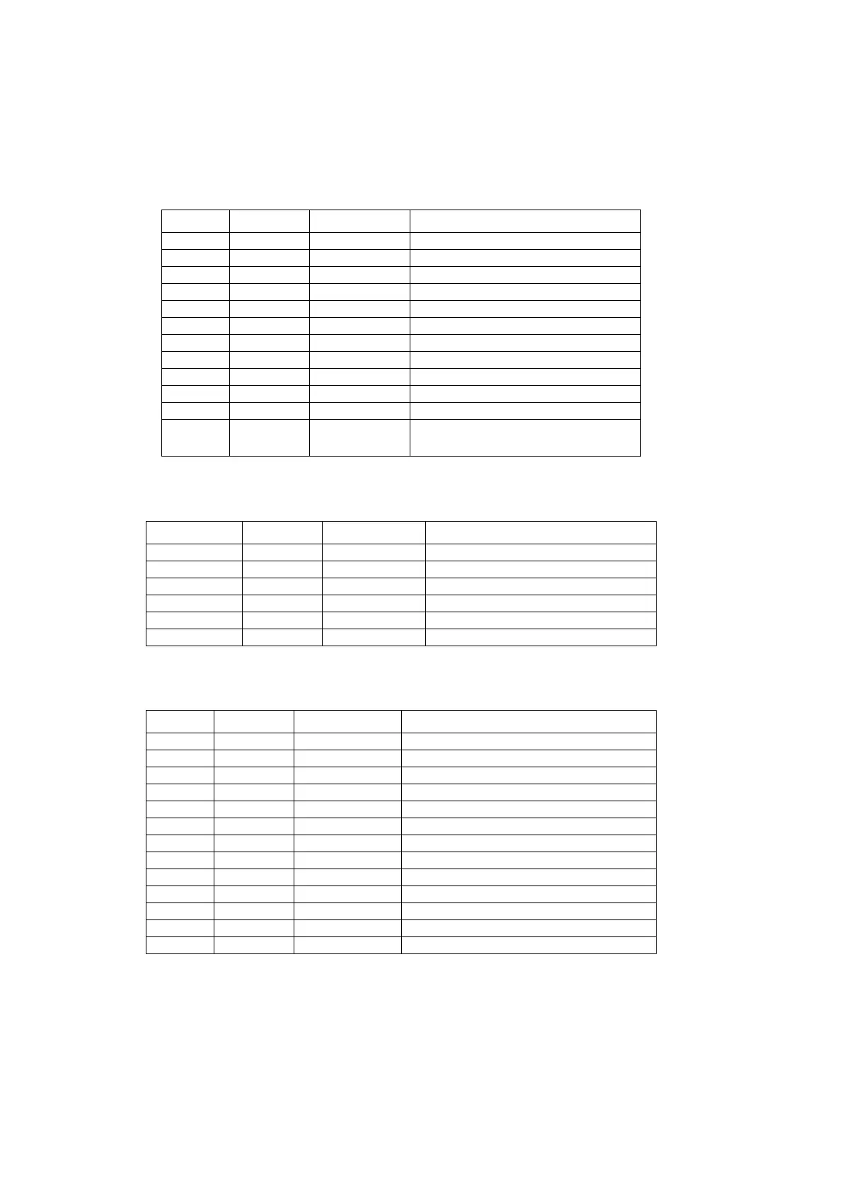
On the DIB board directly on the front:
On the safety relay:
On the ETX base board:
Name Colour Location Function
V6 green DIB-PCB Product Detect
V7 green DIB Mark suppress Control
V8 green DIB Encoder Channel A
V9 green DIB Laser Fan Frequency
V10 yellow DIB Laser Modulation
V11 red DIB Laser Error
V12 yellow DIB Bypass Relay Power Supply
V13 green DIB Encoder Channel B
V14 yellow DIB Mains Wave pos. AC
V15 yellow DIB Mains Wave neg. AC
V16 green DIB Ready Chain FB
V17 orange DIB Key Switch position "Laser
start"
Name Colour Location Function
LED Power green Safety Relay Supply voltage
LED In1 green Safety Relay Input status, channel 1
LED In2 green Safety Relay Input status, channel 2
LED Out green Safety Relay Switch status, safety contacts
LED Reset green Safety Relay Reset circuit
LED Fault red Safety Relay Error
Name Colour Location Function
V1 green ETXB-PCB FPGA Hardware-Design loaded
V2 yellow ETXB-PCB HDD Activity
V3 green ETXB-PCB 5V present
V4 green ETXB-PCB 3.3V present
V5 green ETXB-PCB 2.5V present
V6 green ETXB-PCB 1.26V present
V7 red ETXB-PCB ETH 1 Link
V8 green ETXB-PCB ETH 1 Speed (10/100 MBit)
V9 yellow ETXB-PCB ETH 1 Activity
V10 yellow ETXB-PCB ETH 2 Link
V11 red ETXB-PCB ETH 2 Speed (10/100 MBit)
V12 green ETXB-PCB ETH 2 Activity
V13 green ETXB-PCB DSP application loaded
 Loading...