8. Fuel system
144
Droop parallel Operation mode (Manual
paralleling)
• Definition: Engine speed on the decrease against
Engine load on the increase.
DROOP(%) = {(No Load Speed - Full Load Rated
Speed) x 100} / Full Load Rated Speed
• Description: Droop is typically used for the l
oad
shar
ing and paralleling of engine driven generators.
Without the Droop mode in paralleling system, gener-
ators can be overloaded or motorized.
• Application: For DROOP Operation,
1. Close Droop selector switch between terminals K and
L.
2. When in Droop operation, the engine speed will
decrease as engine load increase. The percentage of
droop governing can be varied with (7) Droop poten-
tiometer. The higher level of droop is achieved
as
t
urning (7) Droop clockwise.
• Droop level requirements above 10% are unusual and
the minimum droop level to keep the stability of spe
ed
dr
oop governor is 2.5% or above.
• After the droop level has been adjusted, the rat
ed
engi
ne speed setting may need to be reset.
Check
t
he engine speed and adjust the speed setting accord-
ingly.
Accessory Input (Automatic Paralleling)
• The Auxiliary terminal N accepts input signals from
load sharing units, auto synchronizers, and other
governor system accessories.
• It is recommended that this connection from accesso-
ries be shielded as it is a sensitive input terminal.
• When an accessory is connected to Terminal N, the
speed will decrease and the speed adjustment must
be reset.
• When operating in the upper end of the control
system frequency range, a jumper wire or frequency
trim control may be required between Terminals G
and J. This increases the frequency range of the
speed control to over 7,000Hz.
Controller LAMP Display (diagnosis)
• Power : When the battery power is connected and
i
nner control power (DC 12V) is achieved, the lap is
on and main controller is ready to function.
• Pick Up : When the voltage between terminals C an
d
D i
s VAC 3.0 or above, the lamp is on.
• Crank : When the engine reaches the preset rate
d
spee
d (idle speed), the lamp is on and relevant rela
y
i
s achieved.
• Run : When the engine reaches the preset rat
ed
spee
d (operating speed), the lamp is on and relevant
relay is achieved.
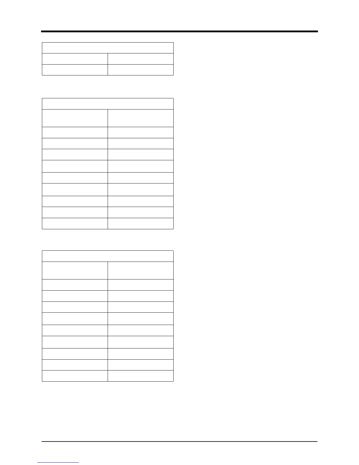
Speed Adjustment 4,800Hz (1800rpm)
Idle Adjustment 2,133Hz (800rpm)
a. CW: Clockwise
b. CCW: Countclockwise
300611-00685
Overspeed
1,725rpm (No. of teeth =
152)
Run lamp Maximum CW
Gain Mid-range (12 O’clock)
Stability Mid-range (12 O’clock)
Starting Fuel
Full CW
a
(Maximum Fuel)
a. CW: Clockwise
Speed Ramping 9 O’clock
Droop
Full CCW
b
(Minimum)
b. CCW: Countclockwise
Adjustment (No. of teeth = 160)
Speed Adjustment 3,800Hz (1500rpm)
Idle Adjustment 2,026Hz (800rpm)
300611-00686
Overspeed
2,070rpm (No. of teeth =
152)
Run lamp Maximum CW
Gain Mid-range (12 O’clock)
Stability Mid-range (12 O’clock)
Starting Fuel
Full CW
a
(Maximum Fuel)
a. CW: Clockwise
Speed Ramping 9 O’clock
Droop
Full CCW
b
(Minimum)
b. CCW: Countclockwise
Adjustment (No. of teeth = 160)
Speed Adjustment 4,053Hz (1800rpm)
Idle Adjustment 2,026Hz (800rpm)
300611-00684