8. Fuel system
146
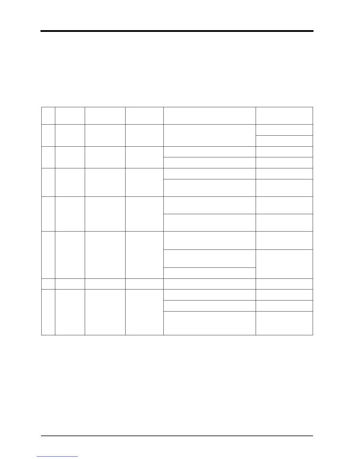
System inoperative
If the engine governing system does not function, the
fault may be determined by performing the voltage tests
described in steps 1, 2 and 3. (+) and (-) refer to meter
polarity. If normal values should be indicated as a result
of following the troubleshooting steps, the fault may be
with the actuator or the wiring to the actuator. In that
case, check the actuator.
Ste
p
Terminal
When to Take
the Reading
Normal read-
ings
Probable Cause of Abnormal Read-
ing
Solution
1 F(+) & E(-)
When the
engine stopped
DC 24V
1.
Check
battery line
2.
Repl
ace battery
2 F(+) & E(-)
When starting
the engine
DC 15V or
above
1. Low battery voltage 1. Check battery line
2.
W
iring error 2.
Repl
ace battery
3C & D
When the
engine stopped
300~1200Ω
(tester ohmme-
ter)
1.
D
efective speed sensor 1.
Check
sensor line
2. Improper or defective wiring to th
e
s
peed sensor
2.
Repl
ace speed sen-
sor
4C & D
When starting
the engine
1.5V or above
(tester AC volt-
meter)
1.
Th
e gap between speed sensor an
d
g
ear teeth too great.
1.
Check
sensor line
2.
D
efective speed sensor
2.
Repl
ace speed sen-
sor
5A & B
When the
engine stopped
3.8~4.5 Ω (tes-
ter ohmmeter)
1. If the voltage reading is belo
w
3.
8 Ω => Short
1.
Check
short/op
en
act
uator
2. If the voltage reading is a
bove
4.
8 Ω => Open wire
2.
Repl
ace actuator
3.
D
efective actuator
6 P(+) & G(-) KEY S/W ON DC 9.5~10.5V Defective speed controller Replace controller
7 F(+) & A(-)
When starting
the engine
DC 9~15V in
normal condi-
tions DC 1~3V
in abnormal
conditions
1.
Speed adj
ustment set too low. 1.
Check
speed setting
2.
Shor
t/open in actuator wiring 2.
Check
actuator line
3.
A
ctuator
3.
Repl
ace actuator
when found to
be
def
ective