11. Electrical System
160
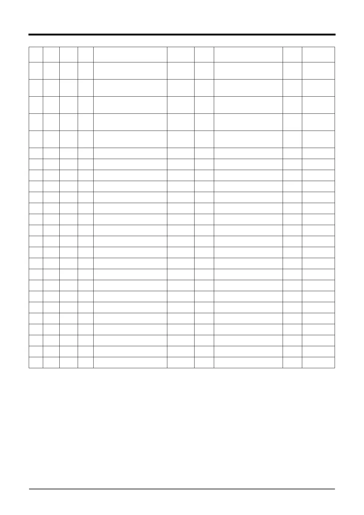
63 825 0.75 Y
Intake air temperature sensor
signal
ECU 8 25
Intake air temperature sensor
(ATS)
1
64 822 0.75 B
Intake air temperature sensor
GND
ECU 8 22
Intake air temperature sensor
(ATS)
2
65 824 0.75 O
Fuel rail pressure sensor RH
PWR
ECU 8 24
Fuel rail pressure sensor RH
(RPSR)
3
66 821 0.75 W
Fuel rail pressure sensor RH
signal
ECU 8 21
Fuel rail pressure sensor RH
(RPSR)
2
67 823 0.75 B
Fuel rail pressure sensor RH
GND
ECU 8 23
Fuel rail pressure sensor RH
(RPSR)
1
Shield drain
(824/821)
68
810 1.5 W Injector 1 "High" ECU 8 10 Injector inline RH (INJR) 1
69 801 1.5 Y Injector 1 "Low" ECU 8 1 injector inline RH (INJR) 2
70 816 1.5 W Injector 3 "High" ECU 8 16 Injector inline RH (INJR) 5
71 807 1.5 Y Injector 3 "Low" ECU 8 7 Injector inline RH (INJR) 6
72 813 1.5 O Injector 2 "High" ECU 8 13 Injector inline RH (INJR) 3
73 804 1.5 G Injector 2 "Low" ECU 8 4 Injector inline RH (INJR) 4
74 811 1.5 W Injector 5 "High" ECU 8 11 Injector inline RH (INJR) 9
75 802 1.5 Y Injector 5 "Low" ECU 8 2 Injector inline RH (INJR) 10
76 817 1.5 O Injector 6 "High" ECU 8 17 Injector inline RH (INJR) 11
77 808 1.5 G Injector 6 "Low" ECU 8 8 Injector inline RH (INJR) 12
78 814 1.5 O Injector 4 "High" ECU 8 14 Injector inline RH (INJR) 7
79 805 1.5 G Injector 4 "Low" ECU 8 5 Injector inline RH (INJR) 8
80 403 1.5 G Air heater relay ECU 4 3 S403 SP1 Splice 403
81
402 1.5 Brn Air heater relay ECU 4 2 S402 SP2 Splice 402
82
403A 1.5 G Air heater relay S403 SP1 Air heater relay 1 1 Splice 403
83
402A 1.5 Brn Air heater relay S402 SP2 Air heater relay 1 2 Splice 402
84
403B 1.5 G Air heater relay S403 SP1 Air heater relay 2 1 Splice 403
85
402B 1.5 Brn Air heater relay S402 SP2 Air heater relay 2 2 Splice 402
86
415 0.75 W Air heater lamp signal ECU 4 15 Inter conn (INT) 27
87 435 0.75 R Air heater lamp PWR ECU 4 35 Inter conn (INT) 28
No.
Wire
Label
Size
(mm
2
)
Color Circuit Description From No. To No. Remark


 To Next Page