13. Installation Guidelines
201
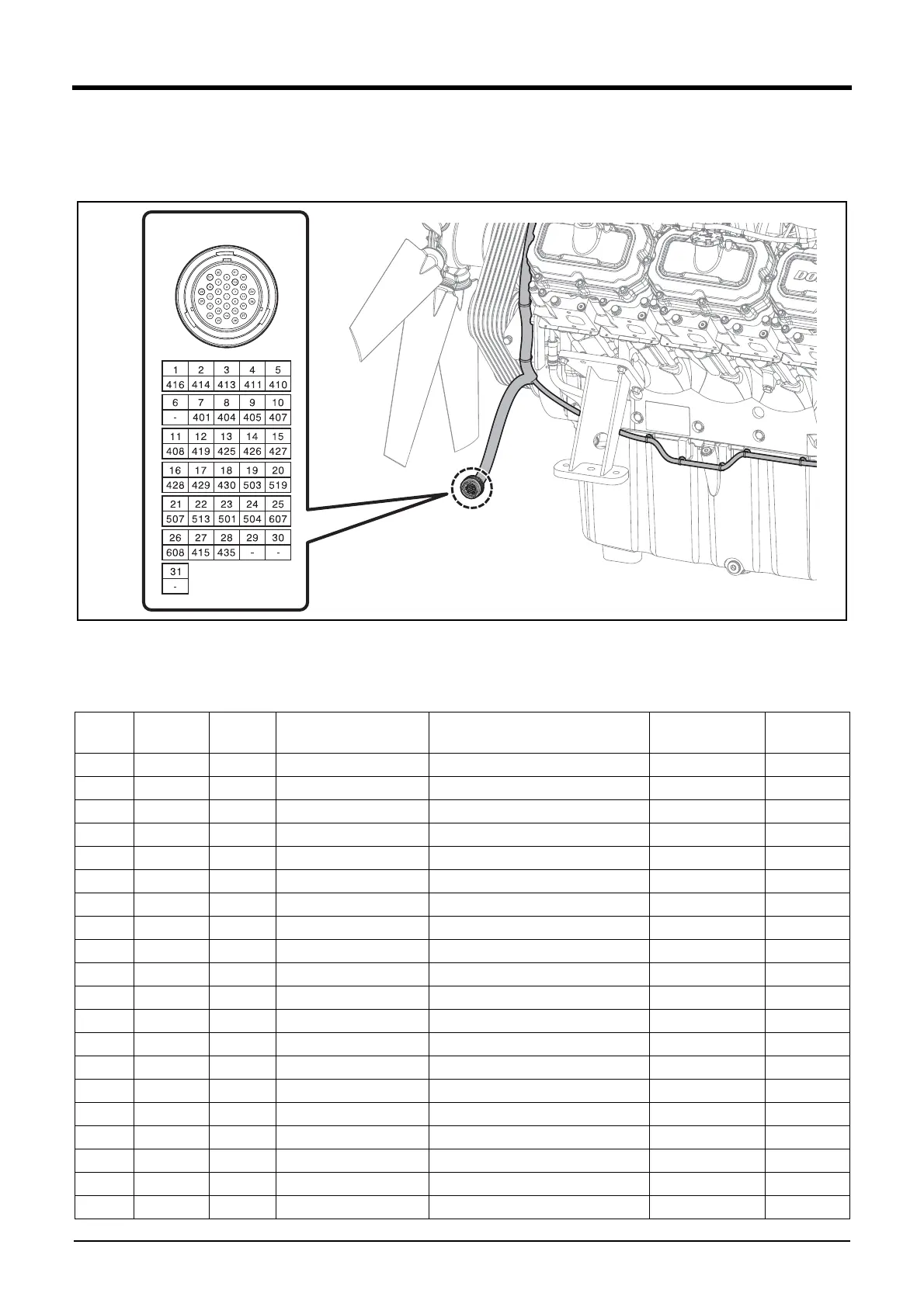
Engine Wire Harness Connector Information
Refer to the engine wire harness connector pin information to connect the connectors to the generator control panel and check
the communications.
EDX22190147
* Mating Connector
Housing: Deutsch HDP24-24-31PE
Pin: Deutsch 1060-16-0122
Circuit
Size
(mm
2
)
Color Insulation Circuit Description From Pin
416 1.5 B FLR7Y-A Battery ground 1 ECU 4 16
414 1.5 B FLR7Y-A Battery ground 2 ECU 4 14
413 1.5 B FLR7Y-A Battery ground 3 ECU 4 13
411 1.5 B FLR7Y-A Battery ground 4 ECU 4 11
410 1.5 B FLR7Y-A Battery ground 5 ECU 4 10
401 1.5 R FLR7Y-A Battery plus 1 ECU 4 1
404 1.5 R FLR7Y-A Battery plus 2 ECU 4 4
405 1.5 R FLR7Y-A Battery plus 3 ECU 4 5
407 1.5 R FLR7Y-A Battery plus 4 ECU 4 7
408 1.5 R FLR7Y-A Battery plus 5 ECU 4 8
419 0.75 Y FLR7Y-A Ignition input ECU 4 19
425 0.75 B FLR7Y-A_TWIST17 Acc. pedal position sensor 2 GND
ECU 4 25
426 0.75 W FLR7Y-A_TWIST17 Acc. pedal position sensor 2 SIG ECU 4 26
427 0.75 O FLR7Y-A_TWIST17 Acc. pedal position sensor 2 PWR ECU 4 27
428 0.75 B FLR7Y-A_TWIST16 Acc. pedal position sensor 1 GND ECU 4 28
429 0.75 Y FLR7Y-A_TWIST16 Acc. pedal position sensor 1 SIG ECU 4 29
430 0.75 R FLR7Y-A_TWIST16 Acc. pedal position sensor 1 PWR ECU 4 30
501 1.5 L FLR7Y-A_TWIST18 Controller area network 1 ECU 5 1
504 1.5 O FLR7Y-A_TWIST18 Controller area network 1 ECU 5 4
503 1.5 B FLR7Y-A T50 input ECU 5 3


 To Next Page