G424F(FE) Service Manual Chapter 5. Engine Management System (EMS) 165
Crankshaft Position Sensor
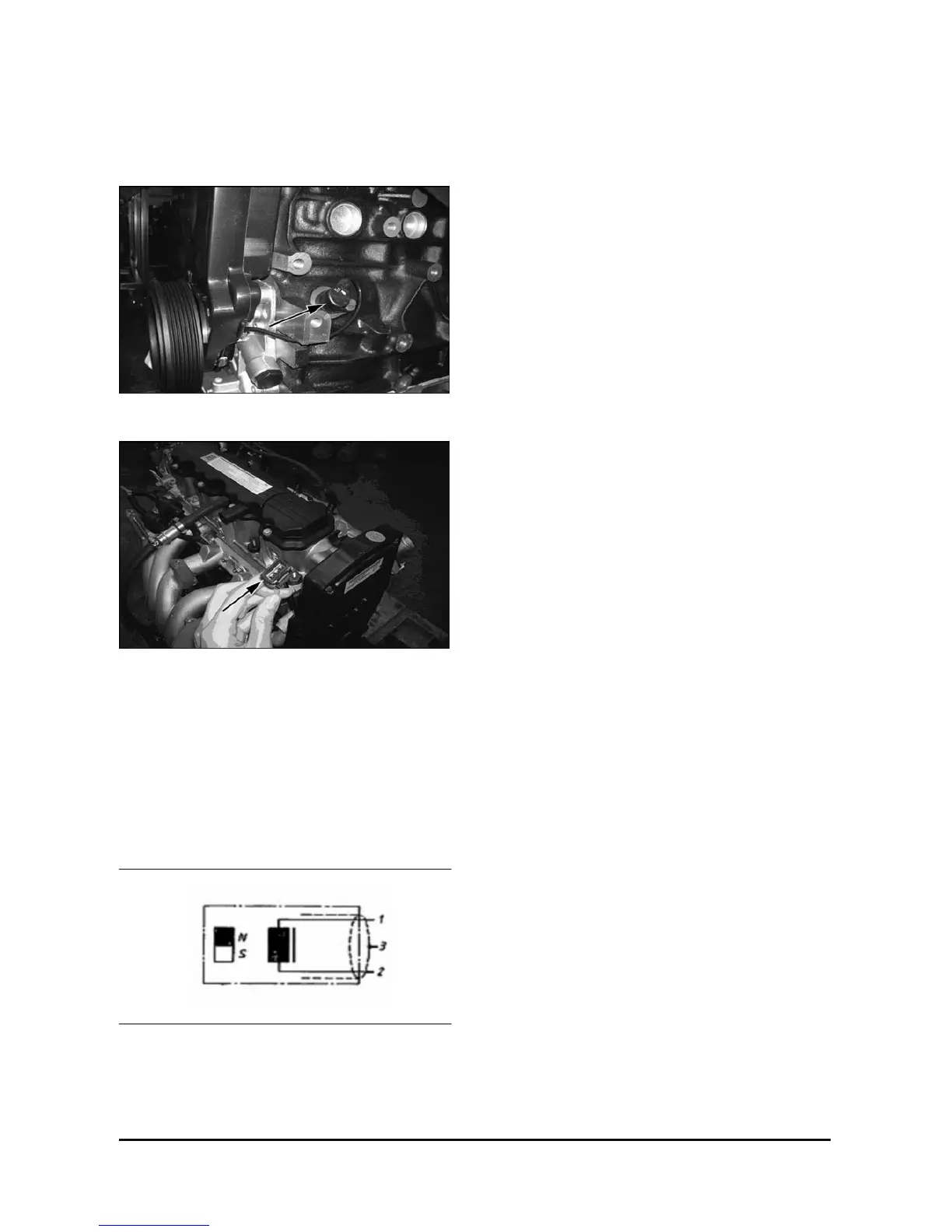
Component Location
Crank Position Sensor
Connector
Specification
Terminal 1: Signal (+)
Terminal 2: Signal (-)
Terminal 3: Ground
Removal
1. Remove the timing belt front cover. See Timing
Belt Front Cover, Remove.
2. Disconnect the crankshaft/rpm sensor electrical
harness.
3. Remove the capscrew retaining the crankshaft /
rpm sensor.
4. Remove the crankshaft/rpm sensor.
Install
1. Install the crankshaft/rpm sensor into the engine
block.
2. Install the capscrew to retain the crankshaft/rpm
sensor. Tighten capscrew to 8 N m◦ (71 lbf ft).
3. Connect the crankshaft/rpm sensor electrical
harness.
4. Install the timing belt front cover. See Timing
Belt Front Cover, Install
 Loading...
