G424F(FE) Service Manual Chapter 3. Engine Mechanical System 43
Installation
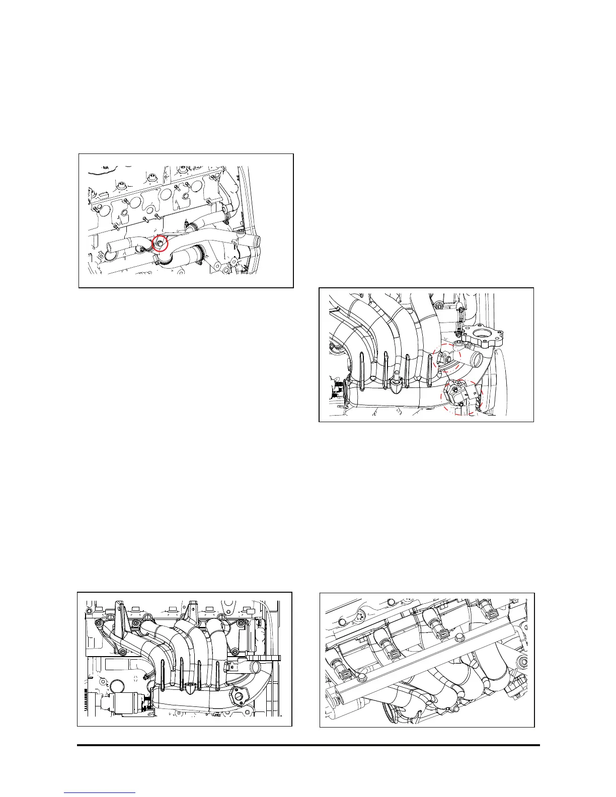
Install or connect
1. Coolant pipe attaching bolt with cylinder block in
its place.
2. With 13mm torque spanner, proper torque; tighten.
Tighten
• Bolts: 18 – 22 N·m (13 – 16 lb·ft.).
3. Hose clamp with torque driver; tighten.
Tighten
• Clamps: 1.5 – 2 N·m (1.1 – 1.5 lb·ft.).
4. A new gasket between intake manifold and
cylinder head.
5. Intake manifold and its attaching nuts, without
tightening.
6. With a 13-mm socket wrench, extension and
proper torque wrench; tighten.
Tighten
• Nuts: 18 – 22 N·m (13 – 16 lb·ft.).
Obs.: Tighten the intake manifold nuts in a
crisscross sequence, from the center to the ends.
7. Put the pipe on the manifold.
8. With a 10-mm socket wrench, extension and
proper torque wrench; tighten.
Tighten
• Bolts: 5 – 6 N·m (3.7 – 4.4 lb·ft.).
9. Insert the TMAP onto manifold with greased o-
ring.
10. With an E-8 socket wrench, extension and
proper torque wrench; tighten.
Tighten
• Bolts: 6– 7 N·m (4.4 – 5.2 lb·ft.).
11. MAP sensor electric connector in the intake
manifold rear area.
12. Insert the fuel rail with injectors in the hole of
manifold and paste oil and grease to o-ring of
injector. (G424FE)
13. With a 12-mm socket wrench, extension and
proper torque wrench; tighten.
Tighten
• Nuts: 18 – 22 N·m (13 – 16 lb·ft.).