13DORMA
1.
2.
4.
1.
5.
2.
1.
2.
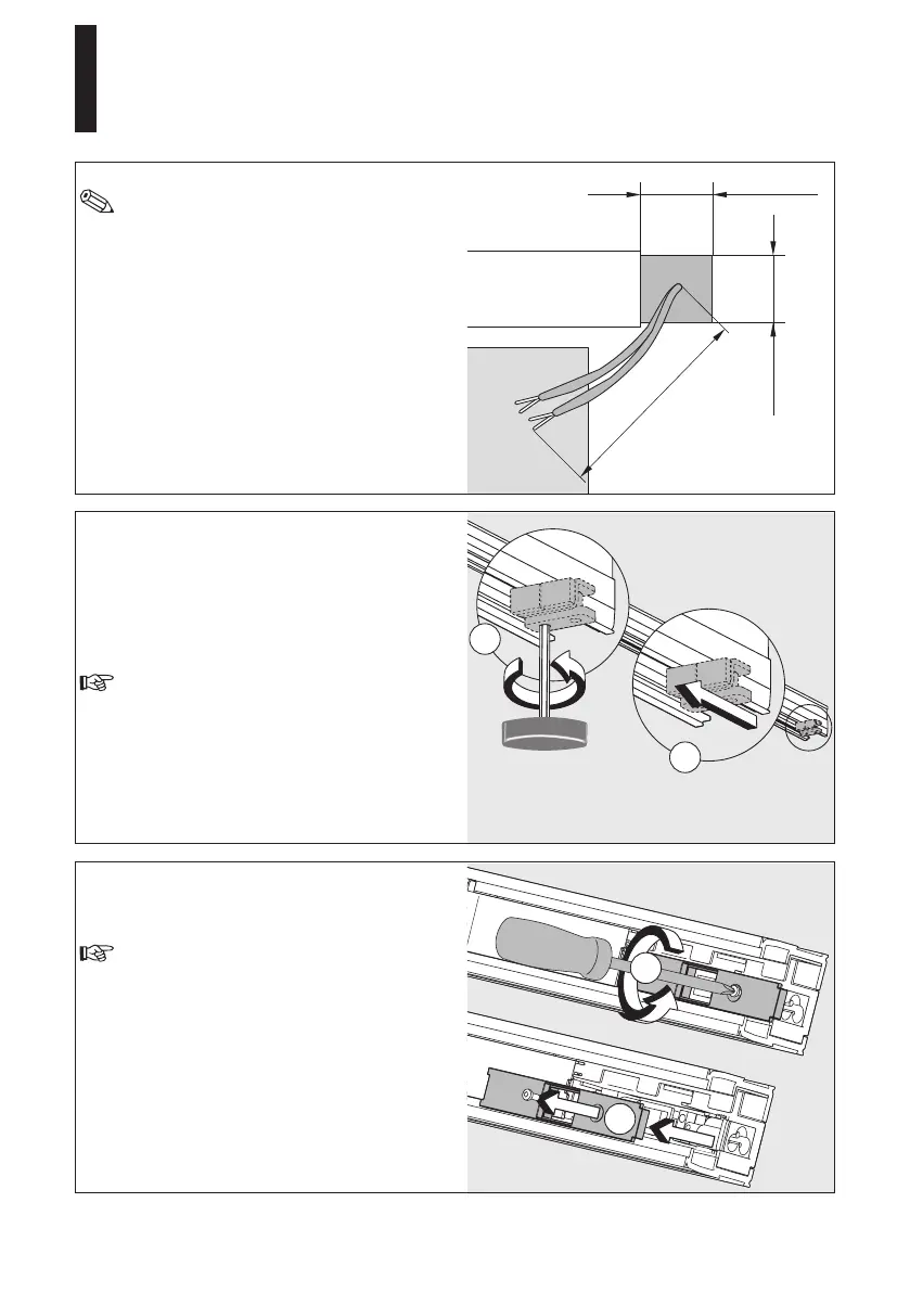
2.4"
(60 mm)
2.4"
(60 mm)
10" min
(min. 250 mm)
In order to facilitate the cabling inside the
operator, all cables should have a length of
at least 10”.
For on-wall mounting
If you want all connection cables that are
coming out of the wall not to be seen after the
installation (only possible with permanent power
supply), they have to come out of the wall within
an area of 2.4” x 2.4” on the side where the
connections of the operator are located.
Installation with permanent power supply: When
the system is installed with permanent power
supply, the internal power supply socket has to
be removed.
Proceed as follows:
Loosenthescrewsattheendstopandmovethe
end stop to the center of the system.
Do not remove or screw down the end stop.
Then loosen the screw in the cover of the power
supply housing and remove the cover (on the
side where the connections are located).
Keep the cover and the screw in a safe
place as you will require it later.
Installation and Maintenance Manual
CS 80 MAGNEO
—
 Loading...