Half/Pack
®
Issued April 2018
Body Controller Software
Copyright 2018, Heil Environmental
Printed in the U.S.A.
Body Controller Software
148
Section 6: Diagnostic Messages and Alarms
6.01: Testing I/O Voltage
To test the voltage at an input or output terminal a Digital Multi Meter is always the best tool. Incandescent test lights
cannot be used to test inputs from certain electronic input devices, the amperage required to light an incandescent tester
may exceed the maximum output of the device. If using a test light it must be an LED type tester.
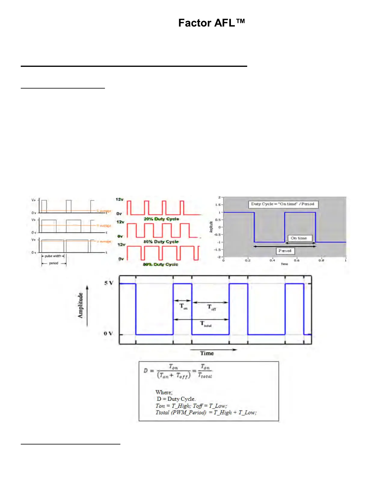
PWM Signal: PWM Controls amount of power, supplied to electrical devices. Main advantage of PWM is that
power loss in the switching devices is very low.
The Average value of Voltage (and Current) fed to the load is controlled by turning the switch
between supply and load ON and OFF at a fast pace. The longer the switch is ON compared to the OFF
periods, the higher the power supplied to the load is. Refer figure below for PWM waveforms:
Voltage can be measured for a PWM signal by using the following equation:
Voltage_Multimeter = (12V * T_High + 0V * T_Low) / PWM_Period
Where PWM_Period = T_High + T_Low (Seconds)
For Ex: T_Low = Test Bulb OFF Time. T_High = Test Bulb ON Time
Figures: PWM Output signal Waveforms
6.02: Monitoring Input Status