CONTACT US AT www.DRpower.com
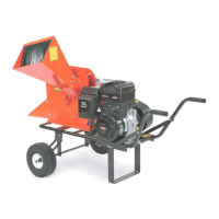
1. the Yellow/Brown and Green/Brown Wires of
the Wire Harness through the hole in the front left
2. ll
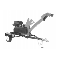
ft rear of the Frame (Figure 64). Do not pull the
Wires through the Bracket Holes.
3. Pull the Green/Brown Wire up through the Wire Hole
in the right rear of the Frame.
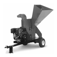
4. Strip 1/2" of insulation from the ends of the
Yellow/Brown wires and Green/Brown wires and twist
the individual wire ends to aid in installation.
NOTE: Ensure that you have the correct Light for each side.
The Side Light of each Light Assembly must face to
the outside of the Chipper.
5. Push the Yellow Wire into the top left hole in the back
of the light socket and push the Brown Wire into the
top right hole (Figure 65).
NO ght
6.
ush the Brown Wire into
the top left hole.
Installing the Tail Lights:
Push
Brown
Wire
Figure 65
Yellow
Wire
Side
Light
Wire
Harness
Figur
Hole in
Frame
e 63
Light
Bracket
Holes
Figure 64
Wire
Rear of
Frame
Left Side
of Frame
Hole
side of the Frame (Figure 63).
Pull the Wires to the back of the Chipper Frame. Pu
the Yellow/Brown Wires up through the Wire Hole on
the le
TE: The wires will be connected and retained in the li
socket holes by spring-loaded connections.
Push the Green Wire into the top right hole in the
back of the light socket and p
or CALL TOLL FREE 1-800-DR-OWNER 57
 Loading...