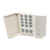
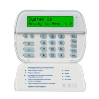
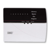
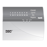
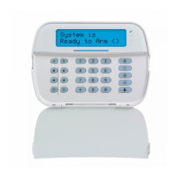
PC1404
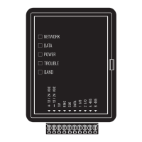
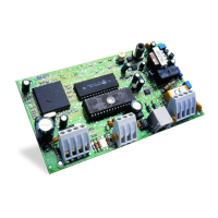
PC520X Aux Power Supply Trouble • Ensure that a the power supply aux power terminal is
not shorted to ground.
• Ensure that the maximum power supply aux current has
not been exceeded.
[4] General System Tamper Tamper input on module(s) open circuit Short tamper terminal to COM terminal on unused modules
connected to KEYBUS (PC5200, PC5204, PC5208,
PC5601).
[5] Module Supervision Panel does not communicate with mod-
ule(s) on KEYBUS
Keypad assigned to incorrect slot
Modules are immediately enrolled and supervised when
detected on the KEYBUS. If a module has been removed, or
if the slot assignment of a keypad has been changed, module
supervision must be reset.
• View the event buffer (via DLS or LCD5500 keypad) to
identify the specific modules in trouble.
• To reset module supervision:
-Enter Programming Section [902].
-Press [#] (wait 1 minute for panel to scan KEYBUS).
• Enter Programming Section [903] to identify modules
connected to the KEYBUS.
[6] Not Used
[7] PC520X Low Battery PC520X battery less than 11.5VDC
Note: This trouble condition will not
clear until the battery voltage is
12.5VDC min., under load.
See [1] Low Battery above.
[8] PC520X AC Failure No AC at PC5204 AC inputs Verify voltage measured across AC terminals is 16-18VAC.
Replace transformer if required.
Trouble [2] AC Failure
AC Failure No AC at panel AC input terminals. • Verify voltage measured across AC terminals is 16-
18VAC. Replace transformer if required.
Trouble [3] Telephone Line Trouble
Telephone Line Trouble Phone line voltage at TIP, RING on main
panel is less than 3V
DC.
Measure the voltage across TIP and RING on the panel:
• No phone off-hook – 50VDC (approx.)
• Any phone off-hook – 5VDC (approx.)
Wire incoming line directly to TIP and RING.
• If trouble clears, check wiring or the RJ-31x phone jack.
Trouble [4] Failure to Communicate
Failure to Communicate Panel fails to communicate one or more
events to central station.
Connect a handset to TIP and RING of the control panel.
Monitor for the following conditions:
Continuous dial tone
• Reverse TIP and RING.
Recorded operator message comes on
• Verify correct phone number is programmed.
• Dial the number programmed using a regular telephone
to determine if a [9] must be dialed or if 800 service is
blocked.
Panel does not respond to handshakes
• Verify the format programmed is supported by the cen-
tral station.
Panel transmits data multiple times without receiving a
handshake
• Verify that the account number and reporting codes are
correctly programmed.
Contact ID and Pulse formats
• Program a HEX [A] to transmit a digit [0].
SIA format
• Program a digit [0] to transmit a digit [0].
Trouble Cause Troubleshooting
 Loading...
