JOB Entry
15
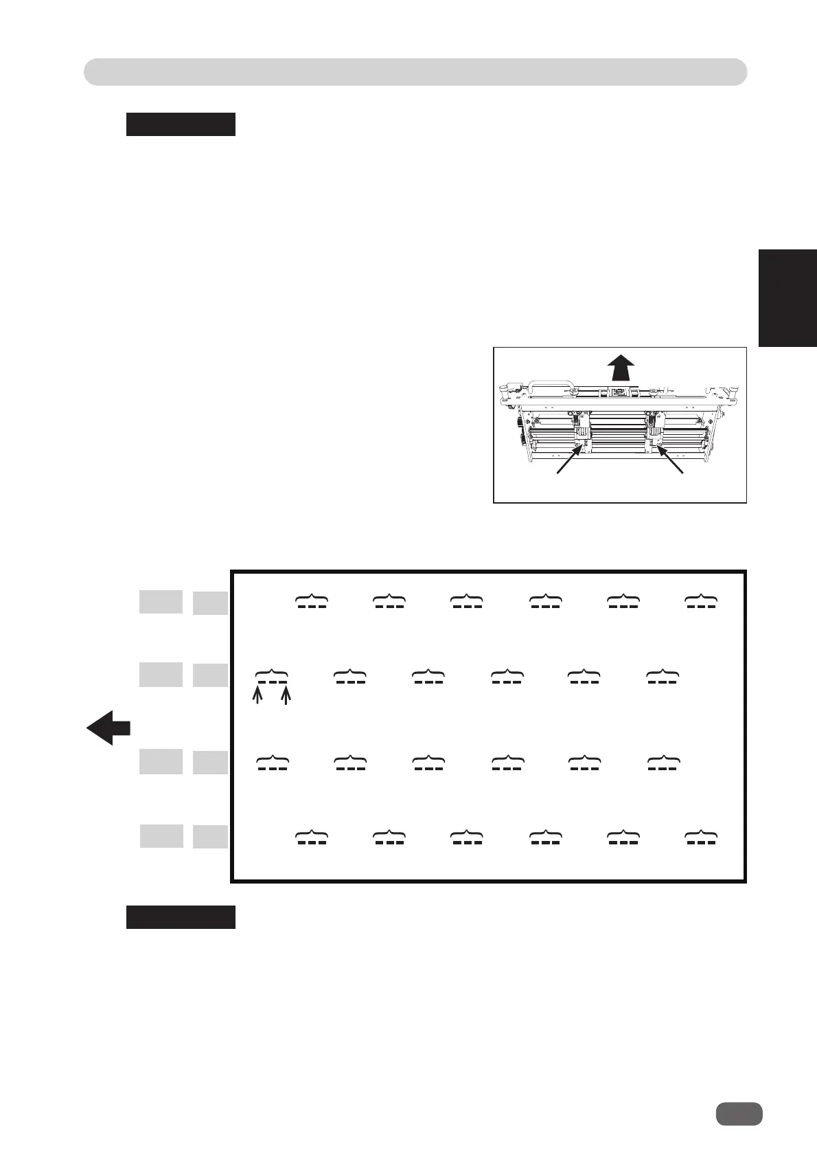
Programming a JOB on the Control Panel
2
Pattern 2
X2-R
Pattern 1
X1-R
Pattern 1
X1-L
X2-L
On Off
Set 1
Set 1
Set 1
Set 1
Set 2
Set 2
Set 2
Set 2
Set 3
Set 3
Set 3
Set 3
Set 4
Set 4
Set 4
Set 4
Set 5
Set 5
Set 5
Set 5
Set 6
Set 6
Set 6
Set 6
● Patterns of processing with
RTM (Rotary Tool Module)
• You can program up to six sets of
On
(a start position) and
Off
(a stop position) in the Y
direction (lengthwise) from the lead edge of a document for each pattern.
One set consists of
On
position and
Off
position. (See above.)
•
X1
and
X2
cannot be programmed at the same processing positions.
• You can set two patterns ([X1-R, X1-L] and [X2-R, X2-L]) in the X direction (crosswise)
from the right edge of a document.
• The distance between X1-R and X1-L, and that between X2-R and X2-L must be 48.0
mm or more.
(
A
in the fi gure on page 12.)
• You cannot set processing positions within 5.0 mm from the document edge and slit in
the X direction.
• The range of values that can be entered is displayed on the LCD panel.
You cannot enter any values outside of the range.
• The
unit L
is on the left side and the
unit R
is on the right side of the
RTM (Rotary Tool
Module)
.
REFERENCE
REFERENCE
Pattern 2
Unit L
Unit R
Document feed
direction
Document
feed
direction