7 | Installation and commissioning
64
D-LX 201/721
Red
Blue
Grey
Pink
Green/yellow
Ready for operation
Yellow
Flame ON
Green
White
Brown
DC network
AC power supply
(accessories)
Functional earth (FE)
Terminal strips
Fieldbus: RS485/Modbus RTU
Range switching
External reset
Analogue output (0/4 ... 20 mA)
Orange
Black
Violet
Protective
earth
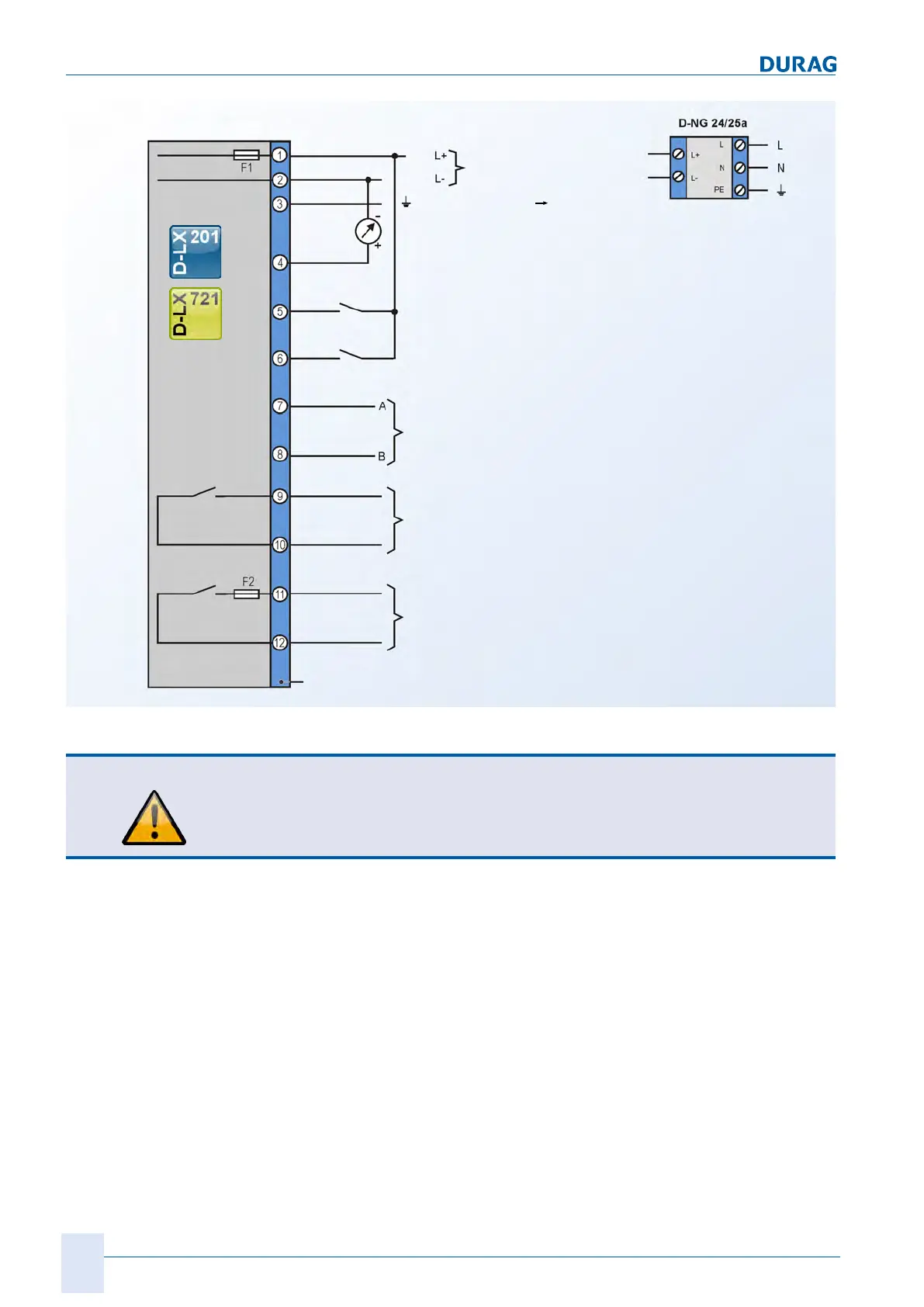
Fig.7.17: Connection diagram for D-LX 201/721
CAUTION
At the "ready for operation" contact output, only non-reactive components may be
operated via an external fuse (for information on the permissible electrical currents,
see section 10 Appendix: Technical data [}93]). This measure provides protection
against contact welding in accordance with EN298.
There is also the option of having the flame monitor fitted with a plug connection (this
option is not available for devices operated in potentially explosive atmospheres). The
connections are then further processed using the connection diagram:

 Loading...