11 | Appendix: Plans and drawings
D-LX 201/721
99
11 Appendix: Plans and drawings
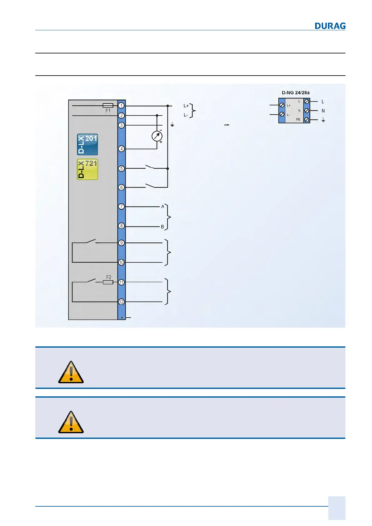
11.1 Connection diagram for D-LX 201/721
Red
Blue
Grey
Pink
Green/yellow
Ready for operation
Yellow
Flame ON
Green
White
Brown
DC network
AC power supply
(accessories)
Functional earth (FE)
Terminal strips
Fieldbus: RS485/Modbus RTU
Range switching
External reset
Analogue output (0/4 ... 20 mA)
Orange
Black
Violet
Protective
earth
Fig.11.1: Connection diagram for D-LX 201/721
CAUTION
At the "ready for operation" contact output, only non-reactive components such as
relay or contactor coils may be operated via an external fuse
This measure provides protection against contact welding in accordance with EN298.
CAUTION
Electrical safety
Once the flame monitor has been installed, the protective conductor must be
connected separately for
Ex devices
. A suitable terminal fitting must be used for
copper protective conductors.

 Loading...