7 | Installation and commissioning
66
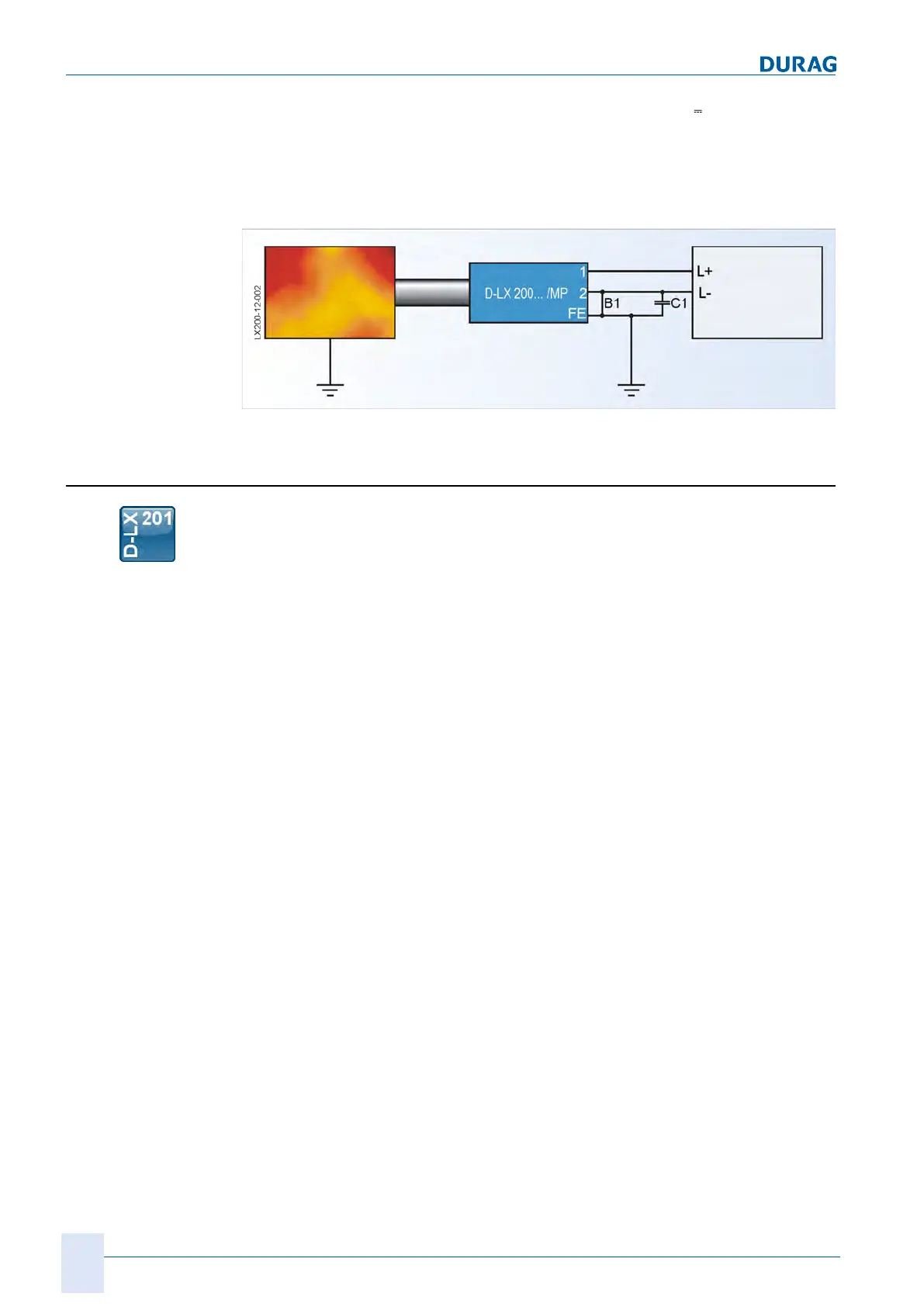
D-LX 201/721
The flame monitor is designed with potential separation. The 24 V
supply voltage
and the internal voltage of the flame monitor are not connected. If faults occur follow-
ing installation, this may be due to a ripple voltage between the 0-V supply potential
and the internal operating voltage.
This can be rectified by capacitive coupling C1 = approx. 100 nF, in the form of a
bridge B1.
Fig.7.19: Ripple voltage is prevented by capacitive coupling.
7.7 Installation, purge air supply
The flame monitor's purge air connection serves to keep the sighting tube and the lens
free from contamination from the combustion chamber. In order for this to be
achieved, an air flow must be directed towards the combustion chamber that is able to
blow off even heavy particles. For combustions with low particle shares (e.g. gas com-
bustions), sufficient purging has been achieved with air speeds of v=1 m/s in a 1¼"
sighting tube (air consumption approx. 3m³/h). Combustions with increased load,
such as coal combustions, must be kept clear with larger volumes of purge air (air
speed v = 3 m/s). The speed of the purge air in the sighting tube is only a reference
value, and may therefore vary from system to system. A ½" screw connection with in-
ner pipe thread is provided on the flame monitor as the purge air connection.
The flame monitor should be checked regularly in order to verify that the lens is clean
and that it is seated securely in the middle part.
If flame monitors need to be mounted onto sighting tubes with high temperature irradi-
ations, then the purge air also acts as a cooling mechanism. In these cases, it is re-
commended that heat insulator D-ZS 117-I (see section 5.2 Accessories [}31]) be
screwed in between the flame monitor and the sighting tube or ball adjustment flange
D-ZS 033-I. It must however always be ensured that the flame monitor does not ex-
ceed the maximum operating temperature of +85 °C.
If an overpressure occurs at the flame monitor sighting tube, it is recommended that
ball valve D-ZS133-I (see section 5.2 Accessories [}31]) be installed between the
flame monitor and the sighting tube or ball adjustment flange D-ZS 033-I. If the lens
becomes contaminated, it can be safely cleaned once the ball valve has been closed.
Purge air with an appropriate upstream pressure is required in order to ensure the de-
sired air flow through the sighting tube (see above for examples). This also depends
on the pressure in the combustion chamber. The differential pressure between the
purge air inlet at the purge air connection and the outlet from the sighting tube into the
combustion chamber is decisive. You can find the required differential pressure in the
following diagram:

 Loading...