8 | Flame monitor settings
74
D-LX 201/721
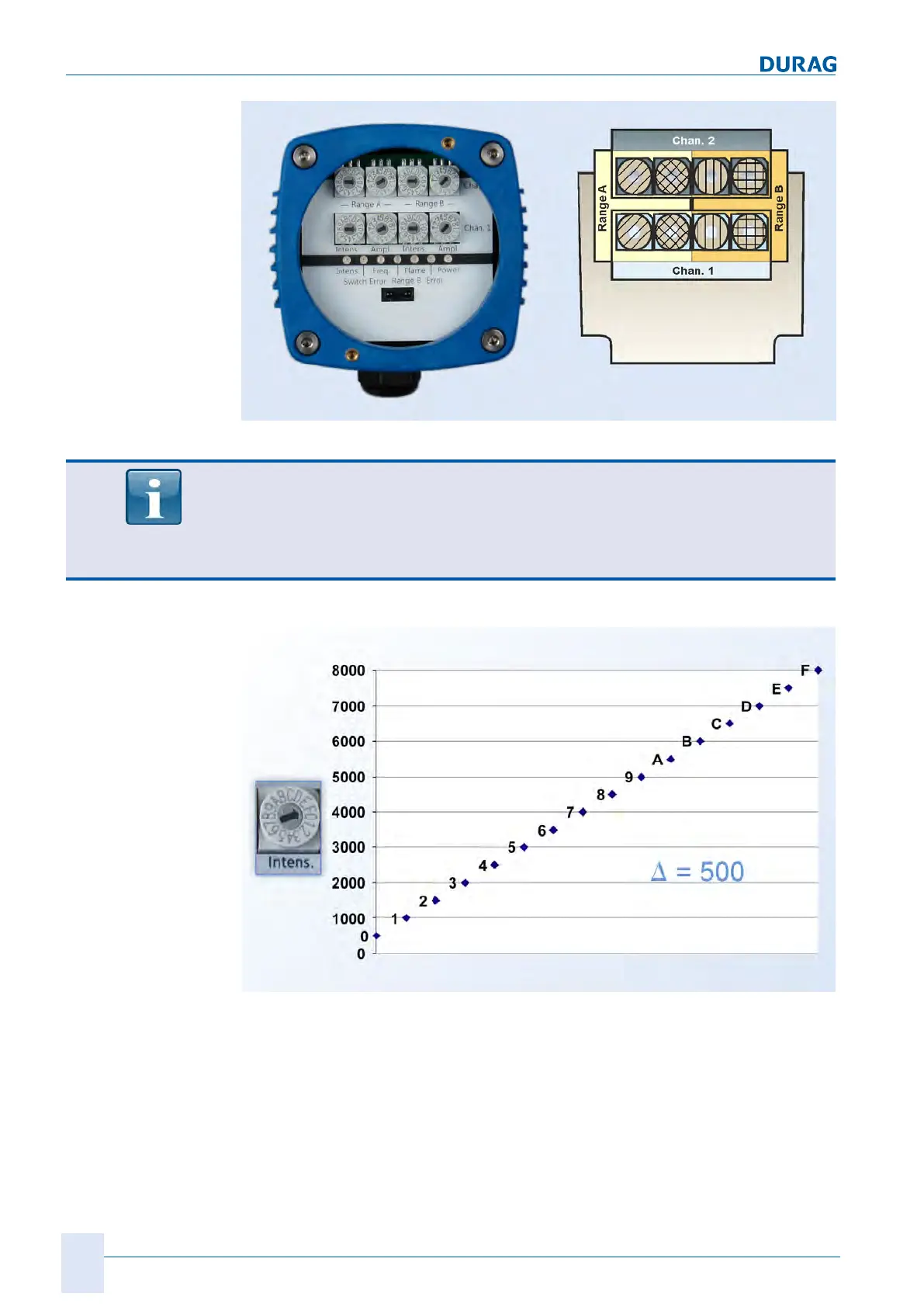
Fig.8.2: Front panel
The rotary switches positioned one on top of the other (right-hand image: rotary
switches with identical hatching) must be set to the
same position
within 8 secs.
In the event of discrepancies between the channels/rotary switches, the red "Switch
error" LED will light up, and an error shutdown (see section 9.5.1 Fault messages
[}91]) will be performed by the flame monitor after 8 secs.
Fig.8.3: Intensity setting
Only those flames with an intensity that exceeds the intensity switching threshold will
lead to a flame ON signal. The scale of the intensity on the Y axis (see Fig.8.3) is se-
lected arbitrarily, and is dimensionless.
After the settings have been made:
Check the seal in the plug-in cover for damage. Position the plug-in cover so that it
lies evenly on the cover. If necessary, rotate the plug-in cover to align it with the cover.
Screw down the plug-in cover with the two socket head screws. This seals the housing
and guarantees the IP protection. The supply voltage can be switched back on again.

 Loading...