8 | Flame monitor settings
D-LX 201/721
85
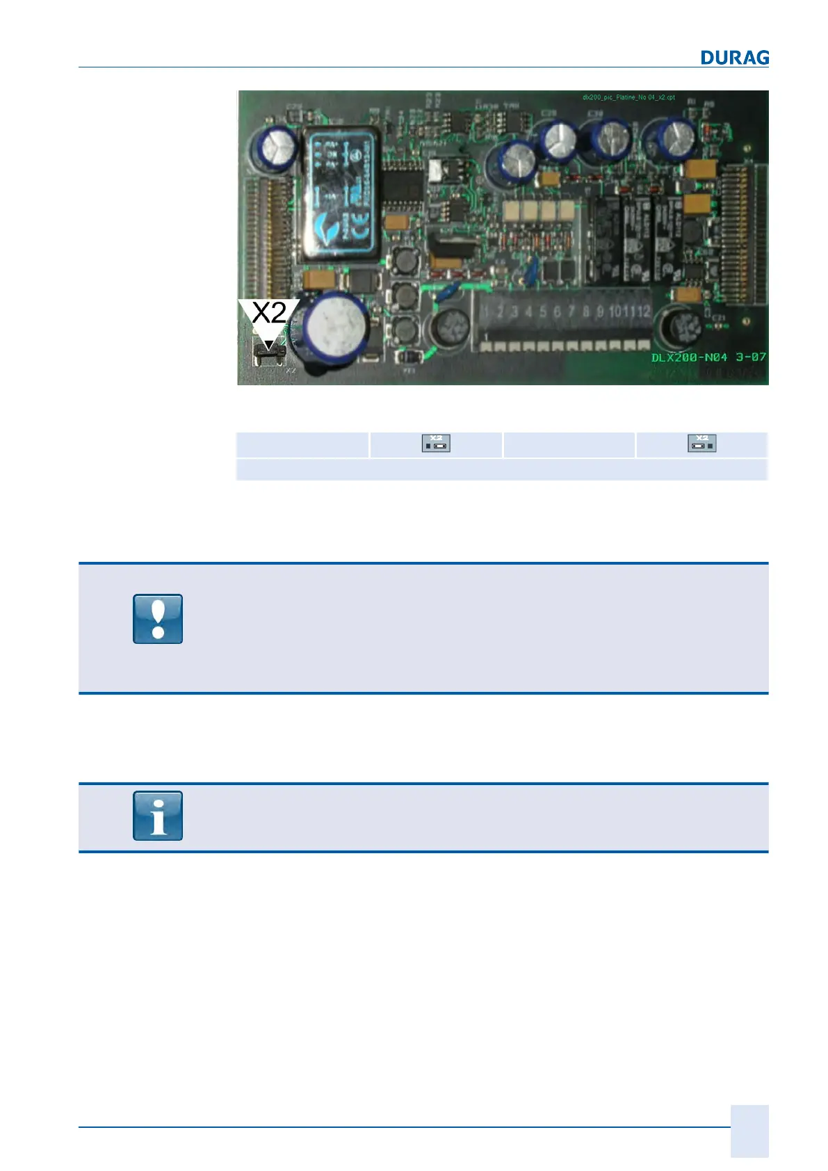
Fig.8.8: Printed circuit board no. 4, jumper X2
Termination ON Termination OFF**
** Standard setting on delivery
Table8.3: Setting the jumpers X2
The flame monitor's Modbus slave address can be set to Modbus slave addresses 1
to 64 using mode switch S5 (printed circuit board no. 2).
NOTICE
Always disconnect the flame monitor before removing the cover.
If live printed circuit boards come loose from their plug connectors when removing the
cover, or if removed printed circuit boards are re-connected under live conditions, this
will cause
serious damage
to the electronic components.
If printed circuit boards have come loose, always make sure that the plug connectors
for the printed circuit boards are not re-connected in the wrong order.
The cover needs to be fully removed in order to set the amplification characteristic and
the Modbus slave address (optional). To remove the cover, the four socket head
screws at the front of the cover will need to be undone.
The Modbus slave address is pre-set to "1" on delivery.

 Loading...