6● DYNALOGIX II (DY 4000) DYNACO USA
30 THE SAFEST CHOICE Slimline Series RevB.doc1
4. Connect the photo-eye wiring to the terminal block. See Figure 6-5.
• Connect the white wire in the grey transmitter cable to terminal 41.
• Connect the shielded wire in the grey transmitter cable to terminal 42.
• Connect the white wire in the black receiver cable to terminals 43.
• Connect the shielded wire in the black receiver cable to terminal 44.
Photo Eye Wiring
M2-00103
06/13/05
T1 T2 1 1 1 1 1 1A X2 X2 2
2
3 4 33 34 41 42 43 44GGG
T3
Figure 6-5: Photo Eye Connections on Terminal Block
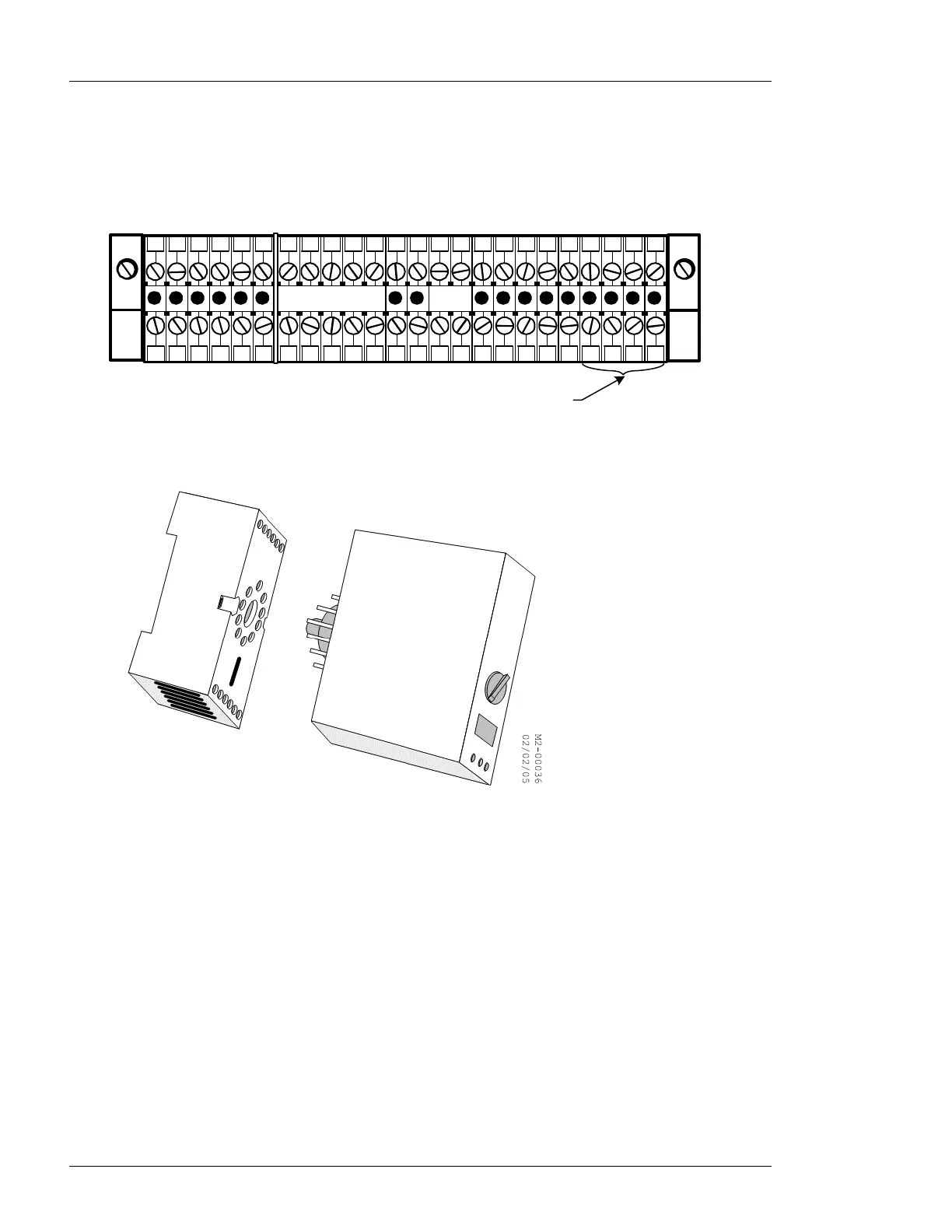
5. Plug the photo eye amplifier into the 11-pin socket. See Figure 4-6
Figure 6-6: 11 Pin Socket for Photo Eye Amplifier
6. Set up the amplifier. See Section Error! Reference source not found.: Error! Reference
source not found. for details.
 Loading...