36
Dynaset Oy | Menotie 3, FI-33470 Ylöjärvi, Finland | tel: +358 3 3488 200 | info@dynaset.com | www.dynaset.com
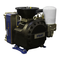
HYDRAULIC SCREW COMPRESSORS
INSTALLATION
Picture 26: Installing hydraulic hoses
NOTE!
Location of P- and T-ports variates between different DYNASET hydraulic
equipment.
Ensure that the hydraulic flow of the base machine is sufficient to run the unit.
At least the minimal flow must be available. READ CHAPTER “10. TECHNICAL
SPECIFICATIONS” for hydraulic flow requirements of your HKR compressor.
> minimal
IN OUT
NOMINAL
FLOW
L/min
MIN MAX
Picture 27: P-line operational hydraulic flow
In case of hydraulic flow being too high. The flow must be reduced either by
dropping down the rotation speed of base machine’s hydraulic pump or using
flow limiter valve. DYNASET PV-SAE priority valve is recommended.
45 cm
3
/tr
27.3 cm
3
/tr
17.1 cm
3
/tr
M
Picture 28: Base machine’s hydraulic pumps