DH200F User Manual
©Dyness reserves the copyright of this document.
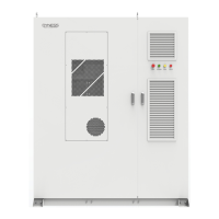
Wiring Wire Instructions
Upon receipt of this product, open the lowest panel on the right side of the cabinet and
will see the wiring area in the electrical compartment as shown below::
Figure 5-9 Wiring Area Diagram
1: PV1 disconnecting switch
2:PV2 disconnecting switch
3:PV3 disconnecting switch
4:Grounding copper row
5: Outlet holes
GRID: Grid-side circuit
breaker
LOAD: Load side circuit
breaker
L1: Firewire L1
L2: Firewire L2
L3: Firewire L3
N: Zero line
P1+: PV1 positive terminal
P1-: PV1 negative terminal
P2+: PV2 positive terminal
P2-: PV2 negative terminal
P3+: PV3 positive terminal
P3-: PV3 negative terminal
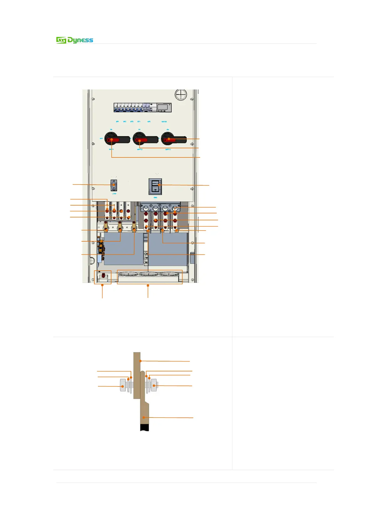
Figure 5-10 Copper End Schematic
1.Copper row
2.Terminal block
3.Bolt
4.Spring pads
5.Flat washers
6.Nut