DH200F User Manual
©Dyness reserves the copyright of this document.
The cable and terminal requirements are as follows:
Table 5-1 Adapted cable/terminal table
Description of installation procedures
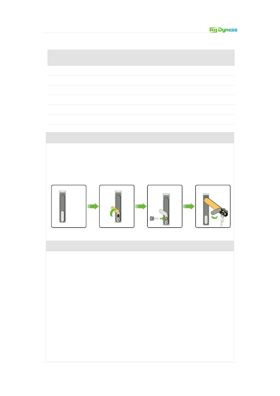
Step 1 Open the cabinet door before connecting the cables
1.Make sure that the equipment is under lock state.
2.Moving the lid up above the locking hole.
3.Getting the key in the door and revolve it clockwise.
4.Rotating the handle clockwise to the position shown in the figure to open the
front door.
Figure 5-11 steps before opening the door
Step2: Cables Preparation
The selected cables must meet the following requirements:
Having sufficient current carrying capacity. The current carrying capacity of a
conductor include the main but are not limited to the following factors:
Environmental conditions
Type of conductor insulation material
The way of cable laying
Material and cross-sectional area of cables
The wire diameter of the cable must be selected according to the maximum
current carrying capacity, and the length must have an allowance.
The specifications and materials of three-phase AC output cables should be
consistent.
Be sure to choose flame-retardant cables.
The cables used must comply with local laws and regulations.
The color of the cables shown in this manual are only suggestions. Please select