DH200F User Manual
©Dyness reserves the copyright of this document.
Step 4 Grounding protection
The grounding method must comply with local standards and regulatory require
requirements.
Please consider the actual situation at project site and follow the instructions of the
power station staff during the process of ground connection. After the grounding
connection, the grounding resistance must be measured, and the specific grounding
resistance value must comply with relevant region/local standards and regulations.
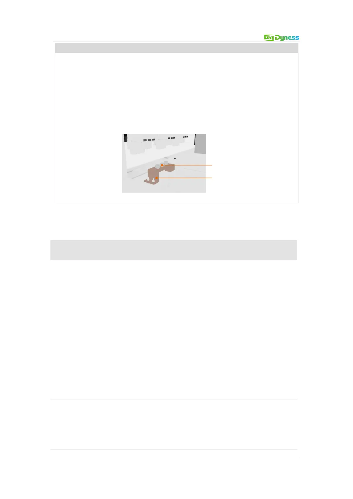
Figure 5-13 Illustration of ground cables
Terminal blocks
Copper rows
Cable wiring steps
Table 5-2 Installation steps for different wiring methods
1.Turn the GRID AC circuit breaker "GRID" to OFF and measure with a
multimeter to ensure that there is no voltage at the terminals.
2.Bring the cable into the inlet hole and enter the AC wiring area of the
electrical cabinet.
3.Ensure that the AC cable connections L1, L2, L3 and N are in the
correct order.
4.Use wire strippers to strip the protective layer of the cable to expose
the copper core.
5.Crimp the OT terminals, refer to "Cable and Terminal Requirements"
in this chapter.
6.Use M10 bolts to fasten the OT terminal to the wiring hole, with a
tightening torque of 21N.m.
7.After the wiring is completed, gently tug the cable to ensure that
there is a margin.
1. Turn the LOAD AC circuit breaker “LOAD” to OFF and measure with
a multimeter to ensure there is no voltage at the terminals.
2. Bring the cable into the inlet hole and into the electrical cabinet AC
wiring area.
3. Ensure that the AC cable connections L1, L2, L3 and N are in the