EA Technology UltraTEV Plus
2
Operating Manual 2388L015
Page 55 of 66
8.3.6 Detection, Measurement and Localisation of the Partial Discharge
Detection of the Partial Discharge using the Ultrasonic Contact Probe is based on the PD
pattern recognition carried out by operators. The audio signature of a Partial Discharge
detected by the Contact Probe is similar to those obtained using airborne sensors. Special
care has to be taken to distinguish phantom signals from genuine signals caused by surface
PD.
Due to the differing propagation paths of the ultrasonic signals, measurements carried out
using the Ultrasonic Contact Probe cannot be compared against measurements carried out
using airborne sensors. In general signals detected by the Contact Probe are smaller as a
result of the physical properties of the asset and propagation path. Comparisons between
two measurements should only be made on assets of the same type using the same
configuration of the Contact Probe.
8.3.7 Mounting Practices
The Ultrasonic Contact Probe was designed to provide sufficient sensitivity to allow it to be
used to detect low level ultrasonic sources.
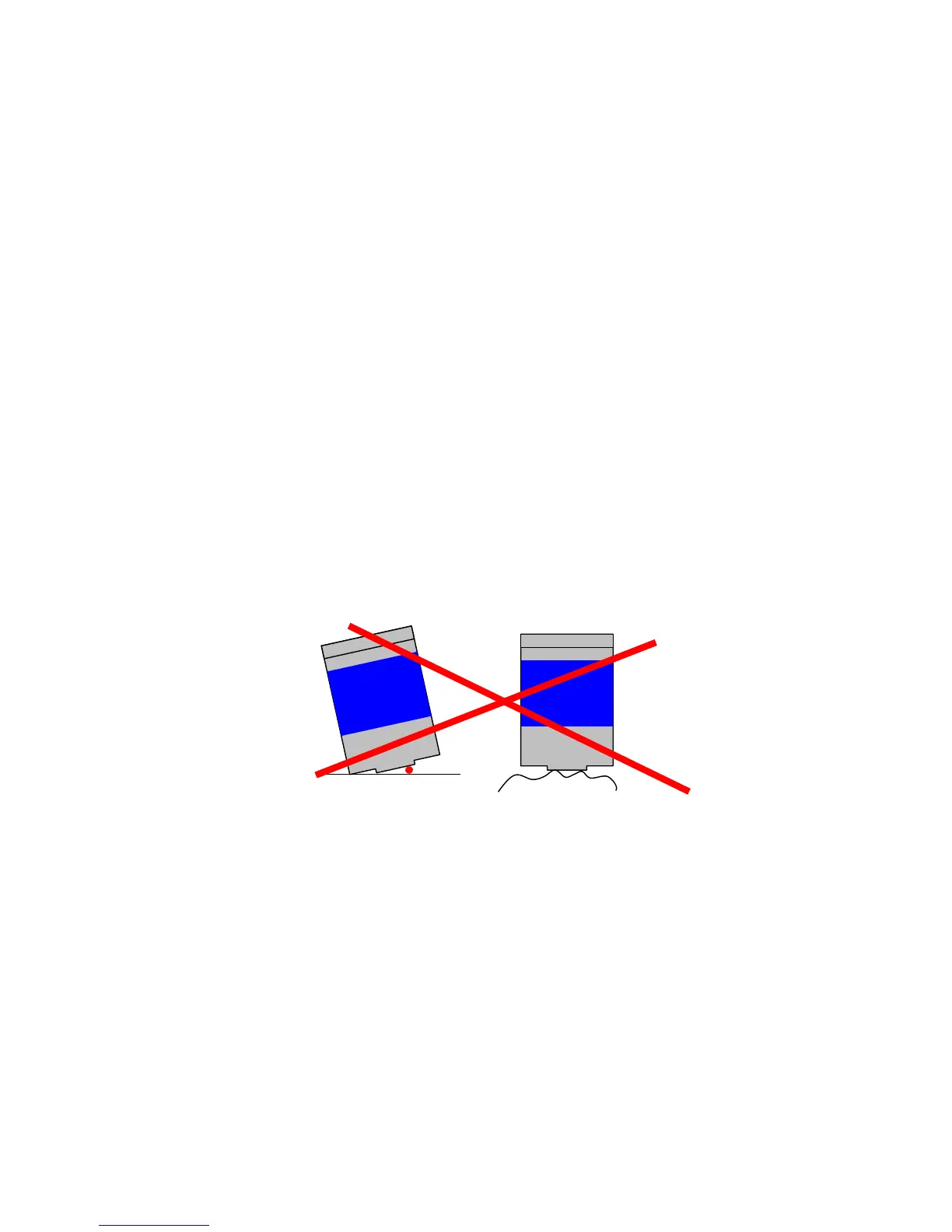
The image below shows scenarios where the Ultrasonic Contact Probe is mounted
ineffectively to the asset enclosure. Any air gap between Sensor Head and measurement
point will effectively attenuate signals to a level where even strong discharges will not be
detected. Therefore before any permanent or temporary installation, the Sensor Head and
asset surface need to be cleaned of any loose or unstable material. If the assets surface is
very rough and uneven this will create air gaps which will result in poor contact between
the Sensor Head and the asset.
1) Dust ingress between Ultrasonic Contact Probe Sensor Head and the asset surface
2) A rough or uneven surface will drastically decrease the amount of signal being
transferred to the Sensor Head
The images below show the correct way of mounting the Ultrasonic Contact Probe to the
asset in order to take a valid measurement. Ideally the Ultrasonic Contact Probe will be
attached to a relatively flat surface using its magnetic clamp. This will eliminate any
phantom noises which are described in the section below.
The second image shows a case where the surface is very rough and uneven. One of the
following couplants may be used:-
Water based – suitable for quick measurement offers very good coupling.
Oil based – suitable for long term monitoring as the oil will not evaporate quickly.