Eaton 9155 UPS (8–15 kVA) User’s Guide 164201553—Rev H0 35
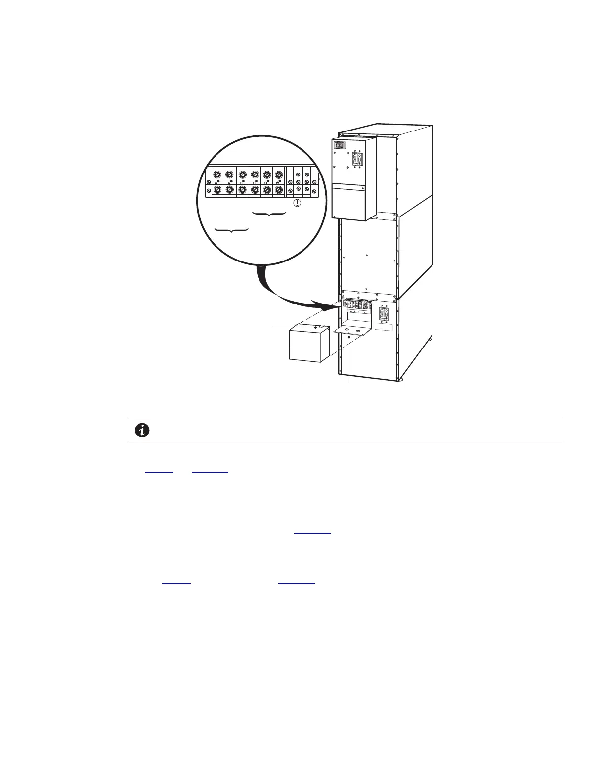
Figure 19. Input Isolation Transformer Hardwiring
Input
Output
L1
L2 (208V)
L2 (240V)
L1
L2
N
GND
Edge Grommet
Pilot Holes in Conduit Landing
NOTE Input neutral is supplied by the input isolation transformer.
12. Wire the output of the input isolation transformer terminal block to the UPS input terminal block (see
Table 4 and Figure 17).
13. Replace the UPS wiring access cover and the input isolation transformer wiring cover.
14. Continue to to complete the UPS installation.
15. On the input isolation transformer, punch one pilot hole in the conduit landing for the input conduit using a
Greenlee punch or similar device (see Figure 19).
16. Install the supplied edge grommet in the top of the input isolation transformer wiring cover.
17. Hardwire the input terminations (TB1-1 through TB1-3) for the input isolation transformer.
See Table 5 for specifications and Figure 19 for a detailed view of the input isolation transformer terminal
block.
18. Punch a hole in the bottom of the MBM/PDM using a Greenlee punch or similar device for wiring access.
Insert the supplied nylon bushing inside the wiring access hole.
19. Continue to to complete the installation.
44..33..44 UUPPSS--MMoouunntteedd BByyppaassss SSwwiittcchh IInnssttaallllaattiioonn
This section describes the Maintenance Bypass Module (MBM) and Power Distribution Module (PDM)
installation. Both modules have a Make-Before-Break (MBB) maintenance bypass switch.
UPS System Installation