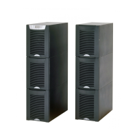
x Eaton 9355 UPS (10/15 kVA) User’s Guide 164201594—Rev H0
Figure 40. Version 2 Bypass Cabinet Load Connections...................................................................................... 55
Figure 41. Version 2 Bypass Cabinet Bypass AC Input Wiring .............................................................................. 56
Figure 42. Lowering the Leveling Feet ............................................................................................................ 57
Figure 43. Stabilizing Bracket with One Cabinet ................................................................................................ 58
Figure 44. Stabilizing Bracket with Two Cabinets .............................................................................................. 58
Figure 45. Stabilizing Bracket with Three Cabinets............................................................................................. 59
Figure 46. Removing the Front Covers............................................................................................................ 60
Figure 47. Battery Panel (Dead Front) ............................................................................................................. 61
Figure 48. Internal Battery Tray Wiring Connections........................................................................................... 62
Figure 49. Internal Battery Tray Wiring Diagram ................................................................................................ 63
Figure 50. Typical EBM Installation (2-High Cabinets Shown) ............................................................................... 64
Figure 51. Front Ground Strap Installation (2-High Cabinets Shown) ...................................................................... 65
Figure 52. UPS Wiring Diagram ..................................................................................................................... 67
Figure 53. UPS with Extended Battery Modules Wiring Diagram .......................................................................... 68
Figure 54. UPS with Input Isolation Transformer Wiring Diagram .......................................................................... 69
Figure 55. Wall-Mounted Bypass Switch (Version 1) Bypass Wiring Diagram........................................................... 70
Figure 56. UPS with Input Isolation Transformer and Version 1 Wall-Mounted Bypass Wiring Diagram ......................... 71
Figure 57. Version 2 Bypass Cabinet Bypass Wiring Diagram – without Maintenance Isolation Switch (MIS).................. 72
Figure 58. Version 2 Bypass Cabinet Bypass Wiring Diagram – with MIS................................................................ 72
Figure 59. UPS with Input Isolation Transformer and Version 2 Wall Mounted Bypass Cabinet Wiring Diagram .............. 73
Figure 60. Communication Options and Control Terminals .................................................................................. 75
Figure 61. Removing the Front Covers............................................................................................................ 76
Figure 62. Installing Communication Cables ..................................................................................................... 76
Figure 63. Removing Knockout Tabs .............................................................................................................. 77
Figure 64. Reinstalling the Front Covers .......................................................................................................... 77
Figure 65. Communication Port ..................................................................................................................... 78
Figure 66. Optional X-Slot Cards .................................................................................................................... 80
Figure 67. Remote Monitor Panel .................................................................................................................. 80
Figure 68. RMP Dimensions ......................................................................................................................... 81
Figure 69. RMP Top Internal View.................................................................................................................. 82
Figure 70. Industrial Relay Card ..................................................................................................................... 83
Figure 71. External Control Terminal Connections ............................................................................................. 84
Figure 72. Eaton 9355 UPS Control Panel ........................................................................................................ 87
Figure 73. Maintenance Bypass Switch........................................................................................................... 94
List of Figures

 Loading...