Eaton 9355 UPS (10/15 kVA) User’s Guide 164201594—Rev H0 ix
LLiisstt ooff FFiigguurreess
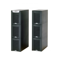
Figure 1. The Eaton 9355 UPS and EBM (3-High Cabinets Shown) ........................................................................1
Figure 2. UPS Cabinet Dimensions (2-High Front and Right Side Views) ............................................................... 14
Figure 3. Extended Battery Module Dimensions (2-High Front and Right Side Views) ............................................. 15
Figure 4. UPS Cabinet Dimensions (3-High Front and Right Side Views) ............................................................... 16
Figure 5. Extended Battery Module Dimensions (3-High Front and Right Side Views) ............................................. 17
Figure 6. UPS Cabinet Dimensions (2 or 3-High Top and Bottom Views) ............................................................... 18
Figure 7. Extended Battery Module Dimensions (2 or 3-High Top and Bottom Views).............................................. 19
Figure 8. 2-High UPS Cabinet Center of Gravity............................................................................................... 20
Figure 9. 2-High EBM Cabinet Center of Gravity .............................................................................................. 21
Figure 10. 3-High UPS Cabinet Center of Gravity............................................................................................... 22
Figure 11. 3-High EBM Cabinet Center of Gravity .............................................................................................. 23
Figure 12. Removing the Stabilizing Bracket Bolts ............................................................................................. 32
Figure 13. Removing the Brackets and Shipping Pad.......................................................................................... 33
Figure 14. Unloading the Cabinet ................................................................................................................... 34
Figure 15. Removing the Pallet...................................................................................................................... 34
Figure 16. Removing the Vertical Bracket ........................................................................................................ 35
Figure 17. Reinstalling the M4 Screws and Remove Pallet Brackets ...................................................................... 35
Figure 18. Removing the Front Shipping Bracket and Shipping Pad ....................................................................... 36
Figure 19. Unloading the Cabinet ................................................................................................................... 37
Figure 20. Removing the Pallet...................................................................................................................... 37
Figure 21. UPS Rear View (3-High Shown) ....................................................................................................... 39
Figure 22. UPS with Input Isolation Transformer Rear View ................................................................................. 40
Figure 23. UPS Terminal Block (3-High Shown) ................................................................................................. 41
Figure 24. Input Isolation Transformer Terminal Block ........................................................................................ 41
Figure 25. Version 1 Bypass Cabinet Front Cover .............................................................................................. 42
Figure 26. Version 1 Internal Cover................................................................................................................. 43
Figure 27. Version 1 Bypass Breaker .............................................................................................................. 43
Figure 28. UPS Rear View (3-High Shown) ....................................................................................................... 44
Figure 29. UPS Terminal Block (3-High Shown) ................................................................................................. 45
Figure 30. Version 1 UPS Output to Bypass Cabinet Wiring ................................................................................. 45
Figure 31. Version 1 Load Connections ........................................................................................................... 46
Figure 32. Version 1 Bypass AC Input Wiring.................................................................................................... 47
Figure 33. Version 2 Bypass Cabinet Front Door and Cover ................................................................................. 48
Figure 34. Version 2 Bypass Cabinet Front Cover Open ...................................................................................... 49
Figure 35. Version 2 Bypass Cabinet Internal Cover ........................................................................................... 50
Figure 36. Version 2 Bypass Cabinet Bypass Breaker ......................................................................................... 51
Figure 37. UPS Rear View (3-High Shown) ....................................................................................................... 52
Figure 38. UPS Terminal Block (3-High Shown) ................................................................................................. 53
Figure 39. Version 2 Bypass Cabinet UPS Output to Bypass Wiring....................................................................... 54

 Loading...