Eaton® 9390 (100–160 kVA) UPS Installation and Operation Manual 164201604—Rev F 2
11..11 UUPPSS SSttaannddaarrdd FFeeaattuurreess
The 9390 UPS has many standard features that provide cost–effective and consistently reliable power
protection.
11..11..11 CCoonnttrrooll PPaanneell
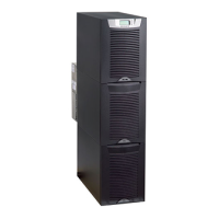
The control panel, located on the 9390UPS front door, contains an LCD and pushbutton switches to control the
operation of the UPS, and to display the status of the UPS system. See Chapter 8 Using the Control Panel for
additional information.
11..11..22 CCuussttoommeerr IInntteerrffaaccee
• BBuuiillddiinngg AAllaarrmm MMoonniittoorriinngg - The facility's alarm system contacts can be connected to six inputs in the
UPS. The UPS uses these inputs to monitor the building alarms in addition to the UPS status.
• AAllaarrmm CCoonnttaacctt - One alarm contact is provided for connection to equipment at the facility, such as a light,
an audible alarm, or a computer terminal. The equipment connected to this contact alerts you to a UPS
alarm.
See Chapter 10 Using Features and Options for additional information.
11..11..33 XX--SSlloott CCoommmmuunniiccaattiioonn BBaayy
A pair of two-slot communication bays is standard equipment. Four optional X-Slot
®
cards can be installed in
the UPS module at any time. See Chapter 12 Communication for additional information.
11..11..44 MMiinnii CCSSBB ((CCoommmmuunniiccaattiioonn SSeerrvveerr BBooaarrdd))
The mini–CSB provides increased logging to 512 events, five additional programmable languages, a real–time
clock, four additional building alarms, and enhanced alarm contact programming.
11..11..55 CCoonnnneeccttUUPPSS--XX WWeebb//SSNNMMPP CCaarrdd XX--SSlloott CCaarrdd
A ConnectUPS™-X Web/SNMP Card is provided as standard equipment and provides remote monitoring
through a Web browser interface, e mail, and a network management system (NMS) using SNMP. See
Chapter 12 Communication for additional information.
11..11..66 AABBMM TTeecchhnnoollooggyy
ABM
®
technology is a three-stage charging system that increases battery service life by optimizing recharge
time, and protects batteries from damage due to high current charging and inverter ripple currents. Charging at
high currents can overheat and damage batteries.
11..11..77 LLaannSSaaffee PPoowweerr MMaannaaggeemmeenntt SSooffttwwaarree
LanSafe® Power Management Software is bundled as part of the Software Suite CD shipped with the UPS.
See Chapter 12 Communication for additional information.
11..11..88 IInnssttaallllaattiioonn FFeeaattuurreess
Cabinets can be permanently bolted to the floor or left standing on leveling feet.
Power and control wiring can be routed through the top or bottom of the cabinet with connections made to
easily accessible terminals. External sensing and monitoring control wire must be installed in accordance with
Class 1 wiring methods. Line-up-and-match battery cabinets are wired through the side panels of the units.
Optional X-Slot connectivity cards are quickly installed at the front of the unit and are hot-pluggable.
Introduction

 Loading...

