141 Eaton® 9390 (100–160 kVA) UPS Installation and Operation Manual 164201604—Rev F
CChhaapptteerr 1155 IInnssttaallllaattiioonn IInnffoorrmmaattiioonn
The information in this chapter is helpful during the planning and installation of the UPS system. This chapter
contains the following drawings:
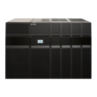
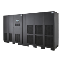
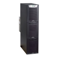
• Figure 79 – 164201604-1 Typical Eaton 9390 UPS System
• Figure 80 – 164201604-2 Physical Features and Requirements
• Figure 81 – 164201604-3 UPS System Oneline Configurations
• Figure 82 – 164201604-4 UPS System Oneline Drawing
• Figure 83 – 164201604-5 Power Wiring Installation Notes
• Figure 84 – 164201604-6 Conduit and Wire Entry Locations
• Figure 85 – 164201604-7 UPS Power Terminal Locations
• Figure 86 – 164201604-8 Interface Wiring Installation Notes and Terminal Locations
• Figure 87 – 164201604-9 UPS Cabinet Dimensions
• Figure 88 – 164201604-10 Optional Remote Emergency Power-off (REPO)
• Figure 89 – 164201604-11 Optional Remote Monitor Panel (RMP)
• Figure 90 – 164201604-12 Optional Relay Interface Module (RIM)
• Figure 91 – 164201604-13 Optional Supervisory Contact Module (SCM)
Installation Information

 Loading...

