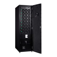
Eaton 93PR 500 kW UPS
User's and Installation Guide
53
The color touchscreen control panel consists of:
• A color liquid crystal touch screen display (1)
• A horizontal row of LED indicators (2)
Before system power up, the panel displays a system status screen similar to the one shown in the figure above.
When the unit powers up, the screen displays as shown in the figure above. When power is applied to the system, the
display advances to the Sign In screen shown Parts of the Touch Screen.
6.2.1. Status Indicators
The four symbols below the display are status indicators. They are colored light emitting diode (LED) lamps,
and they work in conjunction with the alarm horn to let you know the operating status of the UPS.
Table 6-2: Status Indicator
LED Indicator
Status Description
On
The UPS is operating normally and supplying power to
the critical load.
Off The UPS is turned off.
Green Symbol
On
The UPS is in Battery Mode. Because Battery Mode
is a normal condition of the UPS, the Normal indicator
also remains illuminated.
Yellow Symbol —Battery Mode
On
The UPS is in Bypass Mode and the power is supplied
from bypass. The Bypass Mode indicator light is on
while the Normal Mode indicator light is off.
Yellow Symbol —Bypass Mode
On
Please pay attention immediately when UPS has an
alarm. There is the current most important alarm on the
screen. All warning signals will be with alarm sound,
please press any button on HMI to stop it. “Alarm” light
can be lit with other lights.
Red Symbol
6.2.2. Signing In
The touch screen control panel provides an operator interface with the UPS system. The figure below
identifies the display areas discussed in the following sections.
If the level 1 password is enabled, you need to sign in.
1. Press the lock
button in the upper right corner of the screen.
2. Type your passcode and press
OK
.
3. You are signed in. Press
Continue
to return to the previous screen.

 Loading...