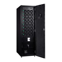
Eaton 93PR 500 kW UPS
User's and Installation Guide
55
Table 6-3: Security Levels and Functions
Level Name Passcode Description
0 USER NONE USER
1 CONTROL 1111 USER + CONTROL
2 CONFIGURATION 0101 USER + CONTROL + CONFIGURATION
3 SERVICE Service Only USER + CONTROL + CONFIGURATION + SERVICE
6.2.3. Using the Main Menu Buttons
The UPS menu bar shown in the figure below allows you to display data in the information area to help you
monitor and control UPS operation. The following table shows the basic menu structure.
Table 6-4: UPS Menu Structure
Main menu Submenu Functions
Home - An overview of UPS operation, including information on load.
Meters
Meters summary A summary of the UPS or sys-tem meters.
Input meters Detailed information on UPS or system input meters.
Bypass meters Detailed information on UPS or system bypass meters.
Output meters Detailed information on UPS or system output meters.
Battery meters Detailed information on UPS or system battery meters.
Mimics
UPS mimic
An overview of UPS operation, including information on load,
efficiency and consumption. If there is an error, an error indi-cator is
displayed next to the affected part. Active events log can be opened
by tapping the error indicator.
UPS module map Module map shows the status of each UPM.
System overview
System overview shows the status and meters summary for each
UPS.
Logs
Active events All active events are displayed.
System log A log of all system events.
Service log A detailed log of UPS opera-tions.
Change log A log of all changed settings and their values.
Controls
System controls Go to bypass, Load Off / Start system
UPS controls Start charger, Run battery test, Shut down UPS / Start UPS
Module controls Start charger, Run battery test /Shut down module / Start mod-ule
Settings Setting group
Configurable user settings. See Chapter 11 APPENDIX A: User
settings on page 84 for de-tails.

 Loading...