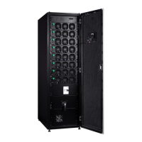
Eaton 93PR 500 kW UPS
User's and Installation Guide
61
6.4.3. Enabling and Disabling the Battery Charger
To turn the battery charger on or off, perform the following procedure:
1. Press the
Controls
button in the main menu. The System controls screen appears.
2. On the
System controls
screen, press UPS controls.
3. Press the
Start charger / Stop charger
button.
6.5. UPM Control Instructions
6.5.1. Adding/Reducing/Replacing Modules Online
N+X is the most reliable power supply configuration at present. N represents the minimum number of
modules of the UPS that the total load needs; X represents the number of the redundant modules of the
UPS, i.e. the number of the fault modules that the system can handle simultaneously. The bigger X is, the
higher the system reliability is. The 93PR can be installed up to 10 modules in its cabinet and the N+X paral-
lel redundancy system can be configured as 1+ 9 or 9 +1 etc multiple different modes. The UPM modules
can be added, reduced and changed online and the quantity of the N and X of the N+X parallel redundancy
system can be changed according to requirement at any time. When the modules fail, if only the quantity of
the fault modules is less than or equal to X, the fault UPM modules can be changed online without affecting
the UPS running.
Options supplied by the N+X parallel redundancy system
The 93PR can be installed from 1 up to 10 UPS modules in its cabinet and the user can choose the N+X
parallel redundancy solution easily. Suppose the load is 80kVA and the optional solution is listed in the
following table:
N+X
Permitted Maximum Power
Permitted Quantity of the
Fault UPS Modules
Apparent Power (kVA) Active Power (kVA)
2+0 120 10 0 0
2+1 120 10 0 1
2+2 120 10 0 2
2+3 120 10 0 3
2+4 120 10 0 4
2+5 120 10 0 5
2+6 120 10 0 6
2+7 120 10 0 7
2+8 120 10 0 8
Note:
• The “Permitted Maximum Power” does not mean that the UPS will be overloaded if this power value is
exceeded. For example, when selecting the 2+2 configuration, the rated UPS apparent power is 120kVA
and active power is 100kW, therefore, if load exceeds the permitted maximum power 80kVA (permitted
maximum power), the UPS will not be overloaded and only the N+X (X=2) structure will be changed.
• The “permitted maximum power” indicates the three-phase power, so the permitted maximum power of
single-phase needs to be divided by three.

 Loading...