6. Function blocks
6.1 Manufacturer function blocks
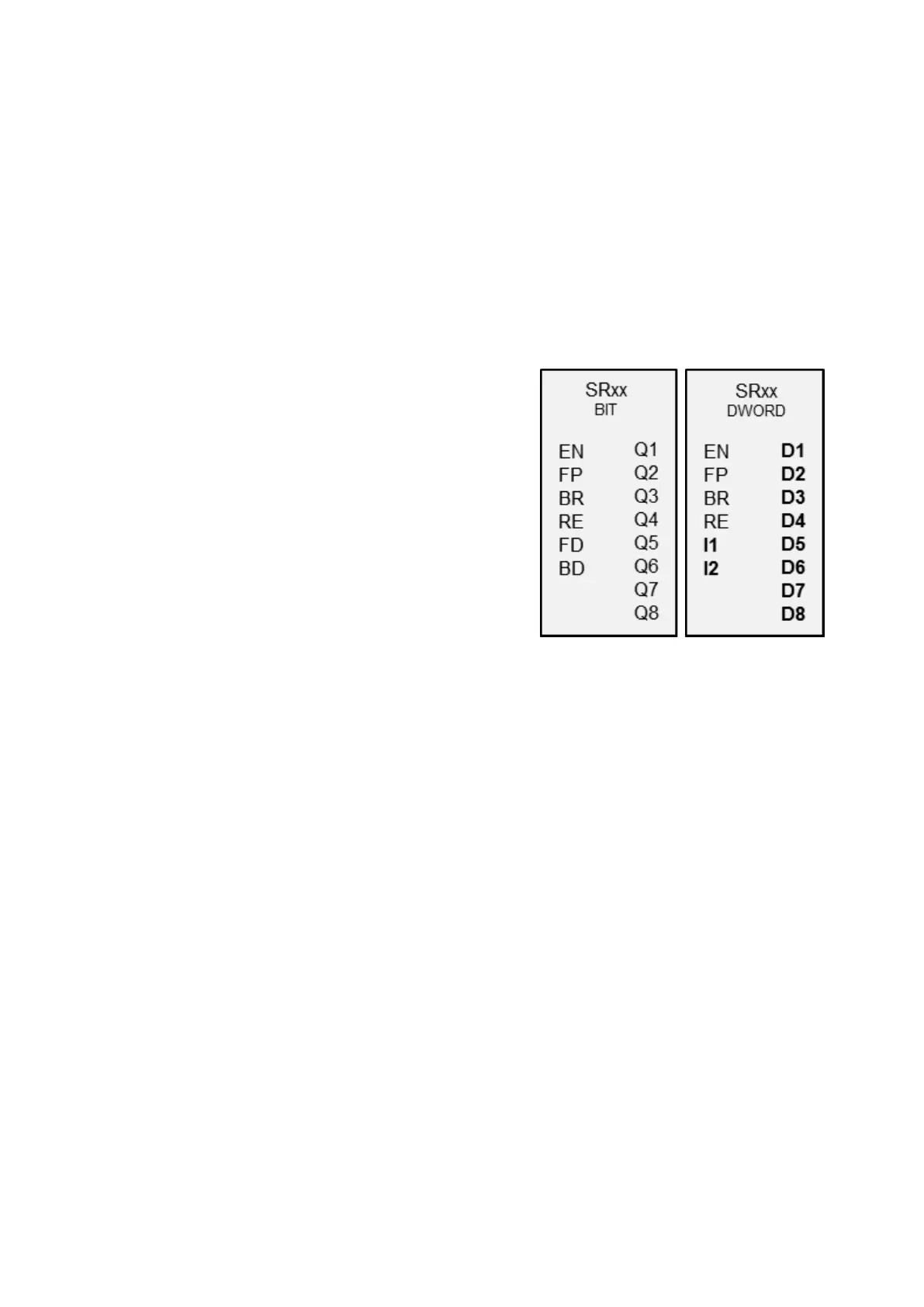
6.1.5.5 SR - Shift register
General
easyE4 base devices provide 32 shift
register function blocks, SR01 through
SR32.
These function blocks can be used to
shift bits or double words by one pos-
ition with every clock pulse. You can
select the BIT or DWORD operating
mode with a parameter. To set the shift
direction, you will need to activate
either function block input FP (forward
pulse) or function block input BP (back-
ward pulse). The values to be accepted
in the shift register are located at dif-
ferent inputs depending on the shift dir-
ection and operating mode.
The shift register has a linear struc-
ture. If, for example, a clock-pulsed bit
operation adds a value is at one end of
the register, another value is dropped
at the other end.
Operating principle
SR function block - shift register (BIT)
A rising edge at FP (ForwardPulse) causes the bit value to be accepted at data input FD
(ForwardData) into the first register field Q1. The original contents of the register fields
are then moved by one field in the direction of the next higher field numbers.
A rising edge at the BP (BackwardPulse) transfers the bit value at the BD (Back-
wardData) data input to the last register field Q8. The original contents of the register
fields are then moved by one field in the direction of the next lower field numbers.
326
easyE4 11/18 MN050009 EN www.eaton.com

 Loading...


