6. Function blocks
6.1 Manufacturer function blocks
The operating mode is determined by selecting different
function blocks:
SR - shift register (BIT) or
SR - shift register (DWORD)
and not with the parameters for the function block as is
usually the case.
If the BIT operating mode is selected, the inputs I1, I2 and
outputs D1-D8 are displayed. They have no function in
BIT mode! If they are assigned operands, these will have
no effect. The wiring of the SR function block (BIT) is car-
ried out in the circuit diagram.
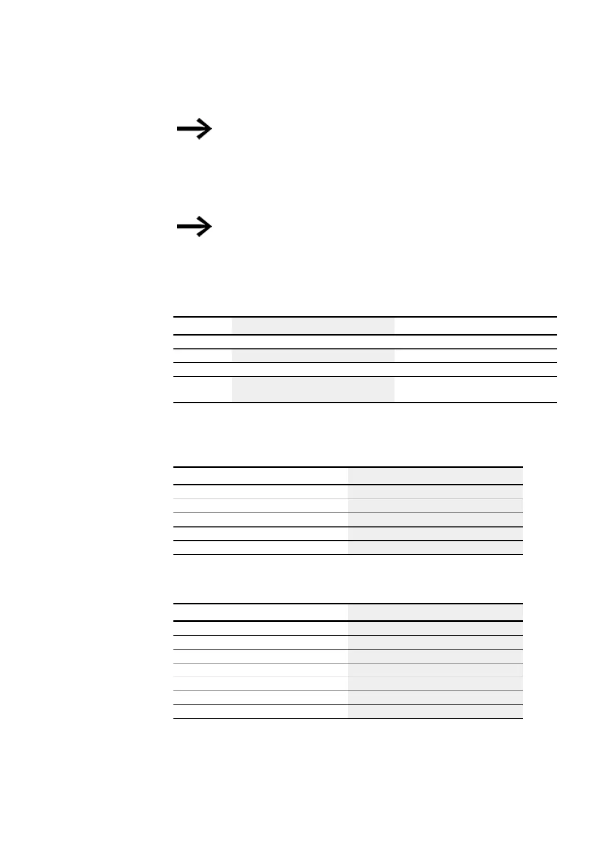
Function block outputs
Description Note
(Bit)
Q1…Q8 Output of the bit register fields 1 - 8
(DWord)
D1…D8 Register values for the shift register 1 through
8
Integer value range:
-2,147,483,648 to +2,147,483,647
Assigning operands
You can assign the following operands to the function block outputs that are numeric
outputs:
Assigning operands Outputs
Constant x
Markers: MB, MD, MW x
Analog inputs IA x
Analog output QA x
Numeric output from another QV FB x
You can assign the following operands to the function block outputs that are bit outputs:
Assigning operands Bit outputs
Constant 0, constant 1 x
M – Markers x
SN - Output bit via NET (send) x
N - Network marker bit x
nN - NET station n marker x
LE - Output backlight x
Q - Bit output from another FB x
Parameter set
330
easyE4 11/18 MN050009 EN www.eaton.com

 Loading...


