6. Function blocks
6.2 Interrupt function blocks
6.2.2.2 Operating principle
You can use function block input TD to set a reference value for a delay you want. You
will need to assign one of device inputs I1 through I8 to the function block as an inter-
rupt source. The first edge at the assigned device input will trigger the interrupt directly
if you did not configure a delay. Otherwise, the interrupt will be triggered after the con-
figured delay elapses. The system will switch from the main program to the interrupt
program and the latter will be processed.
Interaction between main program and interrupt program
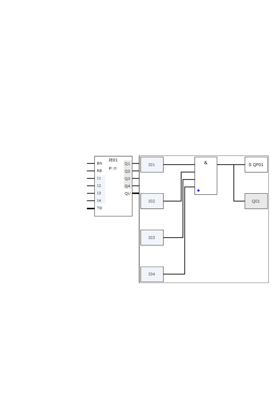
The states of function block inputs IE_I1 through IE_04 are passed to the interrupt pro-
gram, where they can be processed further as I01 through I04.
Function block outputs IE_Q1 through IE_Q4 can be set from the interrupt program. The
corresponding interrupt program outputs are Q01 through Q04.
Main program
Interrupt program
Figure 196: Input and output states being passed between the main program and interrupt program
If an output is defined as a physical output on base device in the parameters for the
interrupt program, the output will be assigned an identifier of QP01 – QP04 and will act
directly on device output Q1 – Q4.
Zur Verarbeitung des Interrupt-Programmes hat der Funktionsbaustein einen eigenen
Merkerbereich von 32 Merker-Bits.
Available functions within an interrupt program
Interrupt programs are not available when using the EDP programming language.
easyE4 11/18 MN050009 EN www.eaton.com
419

 Loading...


