6. Function blocks
6.4 Timing and counter relay example
Confirm the value input with OK.
Press ESC to leave entry.
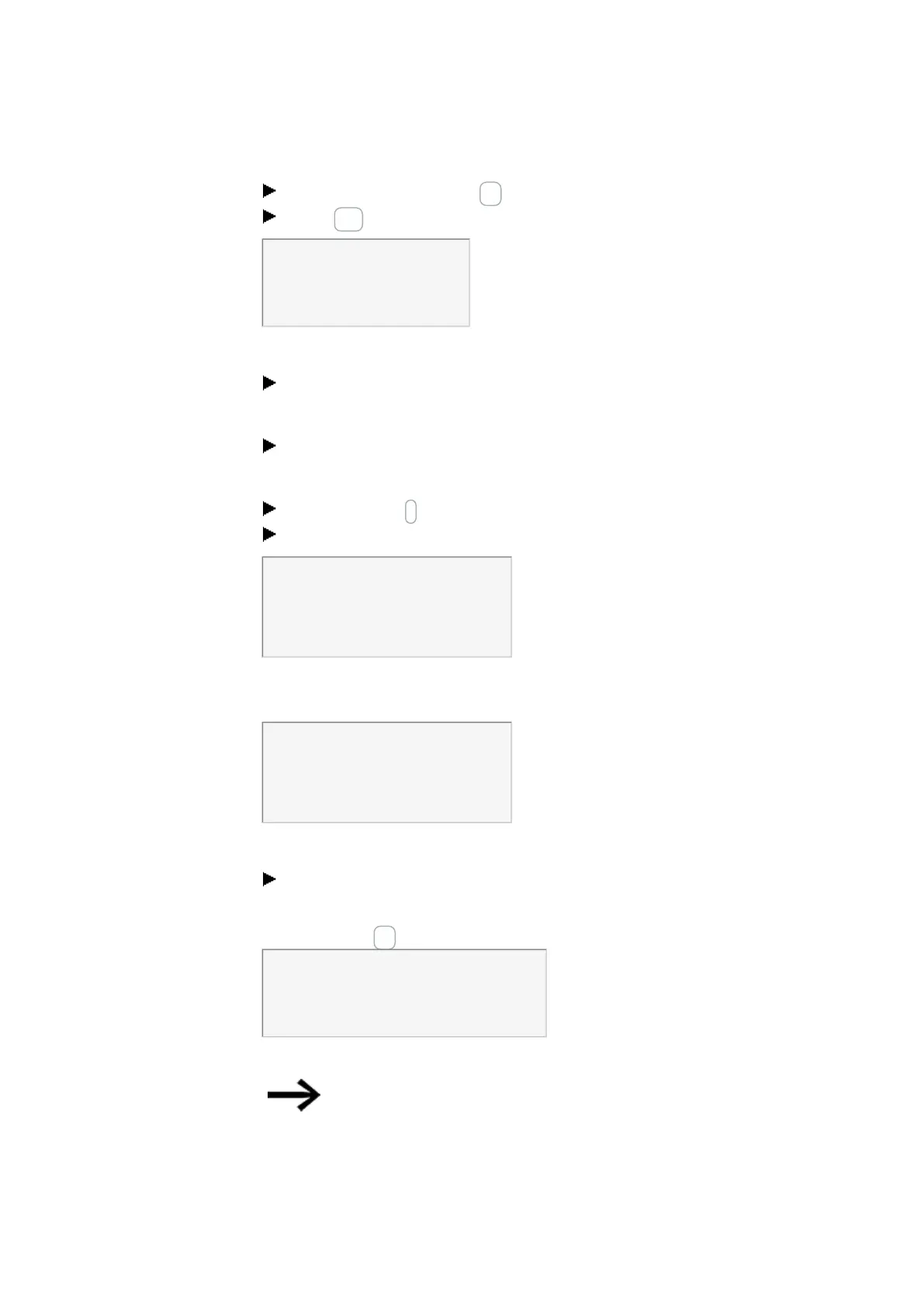
T 01 n S +
>I1 002,000
>I2 002,000
QV>
Figure 220: Enter ParameterT01
Testing the circuit diagram:
Switch easyE4 to RUN operating mode and return to the program.
You can display every parameter set via the function relays menu.
Move the cursor onto C 01 and press OK.
The parameter set for the counter is displayed with actual and setpoint values.
Move the cursor ↓ downwards until you see the value QV.
Switch input IS05. The ACTUAL value changes.
C 01 +
>SH +10
>SL +0
>SV +0
QV>+0
Figure 221: Testing the circuit diagram
If the ACTUAL and upper SETPOINT values of the counter are the same, the timing relay
switches the warning light on and off every 2 seconds.
C 01 +
>SH +10
>SL +0
>SV +0
QV>+10
Figure 222: Testing the circuit diagram
Doubling the flashing frequency:
Select the power flow display T 01 and change the constant of the setpoint time to
001,000.
When you press OK, the warning light will flash at twice the frequency.
T 01 n S +
>I1 002,000
>I2 002,000
QV> 0.550
Figure 223: Doubling the flashing frequency
If the setpoint is a constant, it can also be modified via the PARAMETERS menu.
The actual value is only shown in RUN mode.
456
easyE4 11/18 MN050009 EN www.eaton.com

 Loading...


