Installation_-P_Oval_TypeC_Insertion_r1d -P Probe Physical Installation (Rectangular Ducts)Page 2
EBTRON, Inc • 1663 Hwy 701 S., Loris, SC 29569 • Toll Free: 800-2EBTRON (232-8766) • Fax: 843-756-1828 • EBTRON.com
Step 3. Vertically mounted probes subject to water condensation or accumulation (typically supply air and
outdoor air intakes) should be mounted so that the cable side of the probe is at the top of the duct.
Step 4. Draw a line on the outside of the duct side chosen as the insertion side that is perpendicular to the
edge of the duct and the direction of airflow.
Use a carpenter’s square or similar tool to ensure the probes are in the same plane and
perpendicular to airflow and to locate the edge of the minor axis (shorter dimension) radius that
represents the edge of the duct.
Step 5. Mark a center-point on the line drawn in Step 4 where each probe is located using the spacing
guidelines indicated in Table 1. If more than two probes are provided, continue spacing additional
probes at the ‘b’ interval from the previous probe.
If the probes were ordered for a duct with internal insulation, use the internal dimension of the duct for
‘c’ to calculate ‘a’ and ‘b’, then add the internal insulation thickness to ‘a’.
Step 6. Use the terminal mounting plate [] as a template to locate the position for the four insertion
mounting bracket screws []. Position the terminal mounting plate [] on the duct with the foam
gasket pointing away from the duct so that the center-point marked in Step 5 is in the center of the
center-hole of the terminal mounting plate []. Position the terminal mounting plate [] so that the
center-line notches of the plate are aligned with the line drawn in Step 4. Mark the location of the
four insertion mounting bracket screws [] that secure each insertion mounting bracket [].
Repeat this step for each additional probe center-point, if more than one probe is provided.
Probes less than 18 inches do not have a terminal mounting plate []. Remove the large foam
gasket [] from the probe tube [] and insert a probe into the duct after completing step 7. Use the
probe mounting bracket [] as a template to mark the location for the four mounting screws []. Use
the alignment notches on the probe mounting bracket [] to ensure proper alignment in the duct.
Step 7. Drill a 1-1/8 inch hole at each probe center-point marked in Step 5.
Step 8. Drill appropriately sized pilot holes for each insertion mounting bracket screw [] location (screws
not provided) marked in Step 6.
Step 9. If the probes are provided with the terminal mounting plate [], follow Steps 10 to 14, otherwise skip
to Step 15.
Step 10. On the opposite side of the duct, mark a line perpendicular to the edge of the duct and the direction
of airflow directly across from the line marked in Step 4.
Step 11. Mark a center-point on the line drawn in Step 10 directly across from each center-point marked in
Step 5.
Step 12. Use the terminal mounting plate [] as a template to locate the position for the four terminal
mounting plate screws []. Position the terminal mounting plate [] on the duct with the foam
gasket pointing away from the duct so that the first center-point marked in Step 11 is in the center of
the center-hole of the terminal mounting plate []. Rotate the terminal mounting plate [] so that
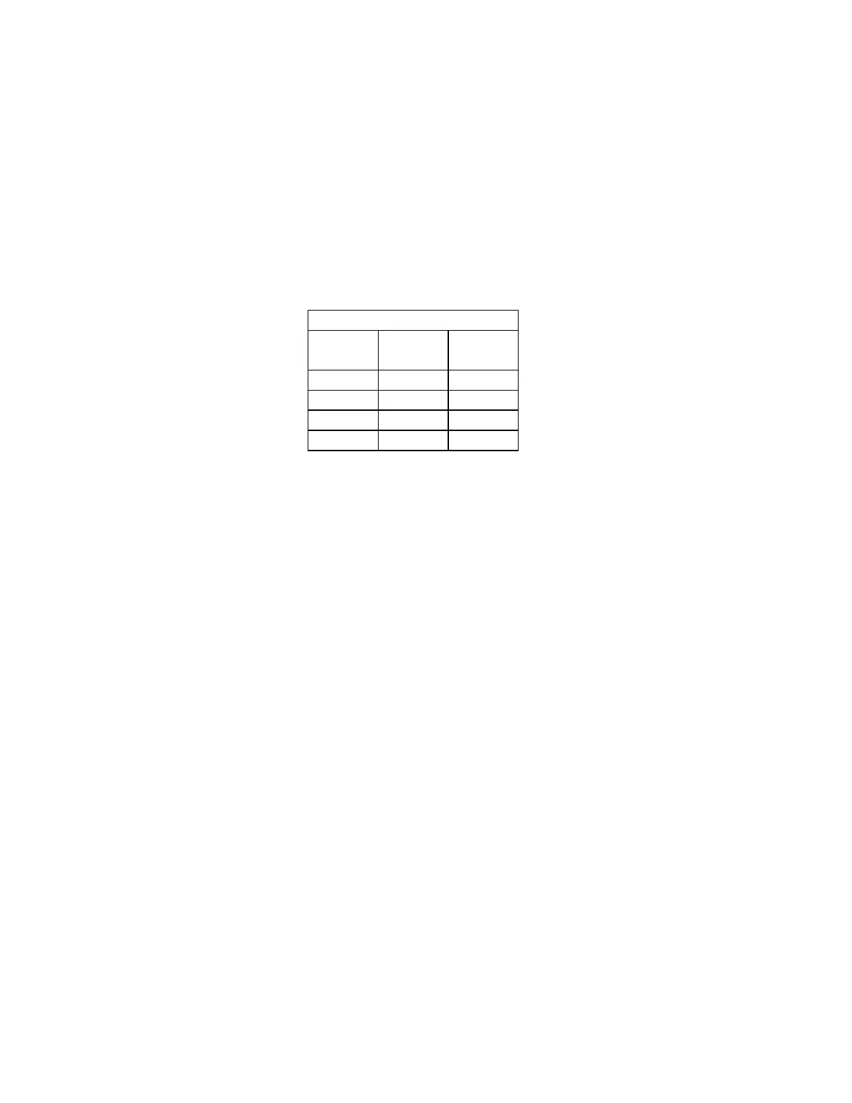
1 c/2
2 c/4 c/2
3 c/6 c/3
4 c/8 c/4
TABLE 1 - PROBE PLACEMENT

 Loading...