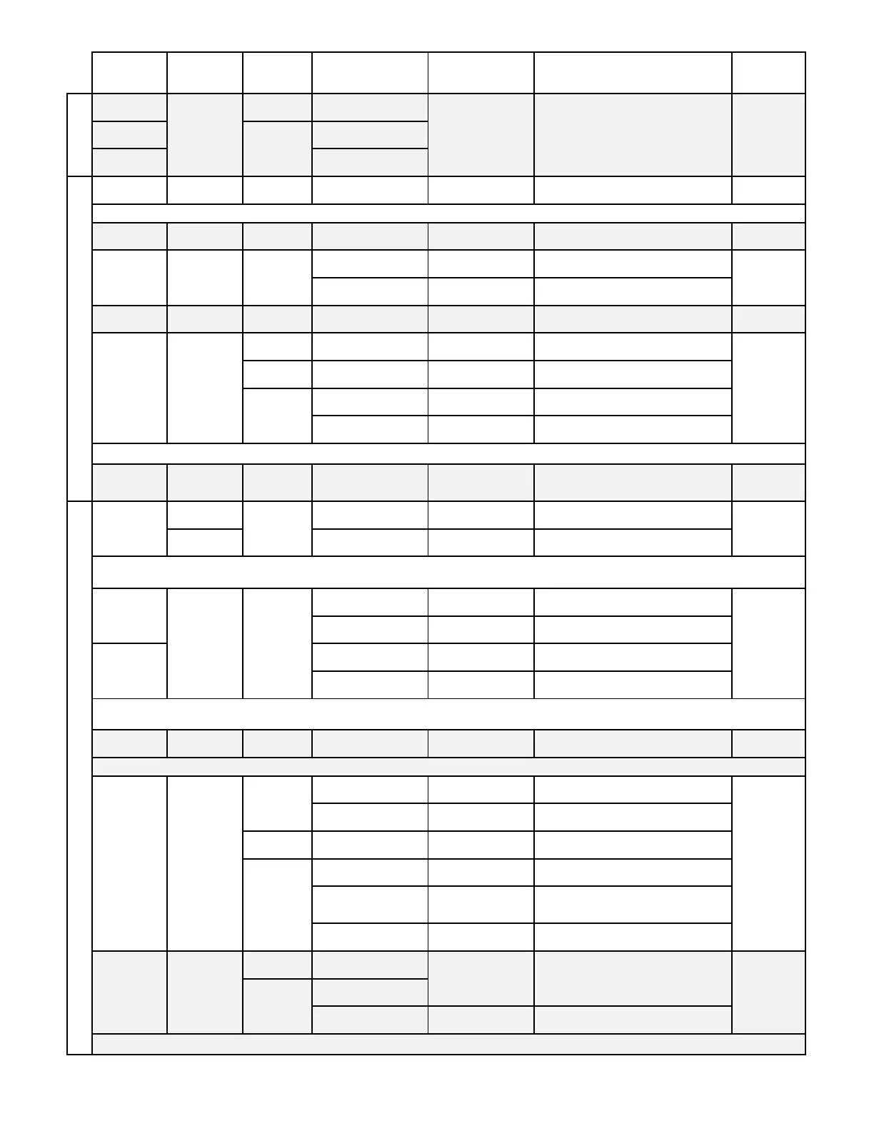
TABLE 3-1 Factory Defaults, Optional Settings and Ranges
Parameter
Special Criteria Default Optional Settings/Ranges Units
EXT CAB All
EXT CAB1 Dual Location 1 of 2
EXT CAB2 Dual Location 2 of 2
LCD DISPL All All ON
OFF
3
LCD NAME All All OFF ON
OFF ON
LOCATIONS=2 ON N/A
LCD TRBL All All ON OFF
-P, -T
CFM [L/s]
4
FPM [m/s]
-U, -F FPM [m/s]
CFM [L/s]
4
DPCONVERT=NO FPM [m/s] CFM [L/s]
DPCONVERT=YES iWG [Pa] None
LCD INTG All All 100
1 to 999 (1 to 750 for HTx202, 1 to 300
for -F/An probe types)
x 300 ms
Advantage IV 4-20mA 0-5V, 0-10V
EB-Flow2 2-10V 0-5V, 0-10V, 1-5V
SW1 set to mA 4-20mA N/A
SW1 set to V 0-10V 0-5V
SW2 set to mA 4-20mA N/A
SW2 set to V 0-10V 0-5V
ON FAIL
7
All All HI LO
AF None
Dual Location 1 of 2 AF1 F1-2, F2-1
-B AF None
/SI, /DI AF None
(SI, /DI only)
AF1 F1-2, F2-1
/An AF None
-P, -T, -U, -F
DPCONVERT=NO
DPCONVERT=YES iWG [Pa] None
Note 8: The default and only option for AO1 UM is FPM [m/s] when the AREA parameter is set to 0 or {null}.
AO1 UM All
FPM [m/s]
CFM [L/s]
8
-B
Note 7: ON FAIL applies to all analog outputs.
AO1 ASGN All
-P, -T, -U
-F
AOUT
5
All
Note 5: Does not apply to GTx116 and GTx108 transmitters without the "e" transmitter model suffix. Set jumpers OUT1 and OUT2 on the main PCB to
the "mA" position for 4-20 mA output or "VDC" for 0-5/0-10V output on HTA104 and HTA202 transmitters.
AOUT1
6
Advantage IV All
AOUT2
6
-B
Note 4: The default and only option for LCD UM is FPM [m/s] when the AREA parameter is set to 0 or {null}.
All 0 0 to 40 [0.0 to 12.2] ft [m]
-P, -T, -U, -F
Note 6: Only applies to GTx116 and GTx108 transmitters without the "e" transmitter model suffix. Switches are located on the output card.
Note 3: When LCD DISPL is OFF the LCD will only show "EBTRON" and the transmitter model code.
LCD SERV All All
LCD UM All
SettingsMenu_r1p Table 3-1 - Page 2

 Loading...