Do you have a question about the ECKELMANN CI 4000 Series and is the answer not in the manual?
Explains safety instructions and hazard warnings, including pictograms and text.
Explains general instructions, including pictograms and text.
Explains warning signs and symbols used in the documentation for safety instructions.
States liability exclusion for non-observance of the operating manual and associated components.
Details special technical knowledge and training required for personnel.
Specifies the intended use of controllers in the CI 4000 series.
Lists and explains the five safety rules according to BGV A3.
Discusses electrostatic sensitive components and handling guidelines.
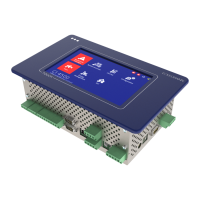
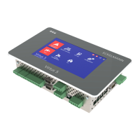
Describes the application of CI 4000 series system centres in control panels.
Details the inputs, outputs, and interfaces of the system centre in its complete design.
Lists and describes the various communication interfaces available on the system centre.
Outlines software version requirements for other E*LDS components to ensure faultless operation.
Provides detailed electrical specifications for the System Centre and SIOX extension module.
Details mechanical specifications including dimensions and cut-out sizes for installation.
Provides information about open source software used in the product.
Lists part numbers for various system centre models and SIOX extension modules.
Lists part numbers for accessories like mounting frames, cables, and modems.
Describes the central functions and tasks performed by the system centre.
Details the different hardware and software expansion stages of the CI 4000 series.
Distinguishes between first start (reset system) and restart of the controller.
Explains how to configure the E*LDS system using LDSWin PC software for local or remote access.
Describes how the controller monitors Modbus nodes and detects component failures.
Details the integration of compact case controllers (UA 30 RC/RS) via Modbus.
Explains integration of external controllers like Dixell and AHT cases via Modbus/COM4.
Describes configuration of digital inputs for alarms, messages, and special functions.
Details the use of digital inputs for special functions like shunt lock and emergency power.
Explains the use of dedicated relay outputs for alarm priorities PRIO1 and PRIO2.
Describes the configuration and functionality of the multi-function AUX relay.
Details how relay outputs can be used for week timers, especially with SIOX modules.
Defines terms used in connection with alarms and messages in the manual.
Explains how to acknowledge alarms and messages system-wide.
Details the priority concept for alarms and messages, divided into 10 alarm groups.
Describes the 15 available destinations for remote alarm signalling.
Explains automatic alarm transmission via Pushover service for CI 4400 and higher.
Explains automatic alarm transmission via E-Mail for CI 4400 and higher.
Describes automatic alarm transmission via modem to various destinations.
Explains how to use Service Mode to suppress remote alarm signalling temporarily.
Details how the controller monitors all E*LDS components on the CAN bus.
Explains the Load Shedding Manager (LSM) for minimizing average demand.
Provides instructions for installing the system centre in a switch cabinet.
Details the default settings for the WDOG and BOOT DIP switches.
Explains the DIN rail mounting of SIOX extension modules and their connection.
Describes how SIOX extension modules are connected to the system centre via power and data cables.
Details the configuration of digital inputs on SIOX modules using jumpers.
Explains how to connect energy, gas, water, and event meters to SIOX modules.
Describes the manual/automatic mode selection for SIOX extension module relay outputs.
Explains the status LEDs for SIOX extension modules.
Describes the status LEDs for the M-bus gateway.
Explains how to perform a hardware reset for unreliable modems.
Details the points to consider when using a GSM modem for SMS transmission.
Describes FAX transmission using an ISDN modem.
Explains the procedure for switching on the system centre by applying mains voltage.
Covers local configuration of E*LDS components via device or service PC.
Provides instructions for cleaning the front panel and touch screen.
Explains that user battery replacement is not envisaged and device must be sent for replacement.
Describes how to load future software versions into the system centre via firmware update.
Shows the system centre in its complete design with terminal connections.
Details the terminal assignments for the 230 V AC power supply connection at the bottom of the device.
Details the terminal assignments for the two digital inputs used for monitoring and measuring.
Describes the terminal assignments for the PRIO1/PRIO2 and AUX relay outputs.
Details the terminal assignments for the CAN bus segments CAN1 and CAN2.
Details the terminal assignments for connecting SIOX extension modules.
Describes terminal assignments for COM3/Modbus (RS485) for connecting controllers.
Lists terminal assignments for various communication interfaces.
Details terminal assignments for SIOX digital inputs (24V AC/DC / 230V AC).
Details terminal assignments for the 8 relay outputs on SIOX extension modules.
Details terminal assignments for SIOX module interfaces like power supply and data ports.
Describes local operation using the touch screen on the device.
Explains access and configuration via LDSWin PC software using USB or COM1.
Details connection and communication via CAN bus to PC adapter.
Covers remote access via LAN using LDSWin or VNC.
Explains how to operate the system centre directly at the device using the touch screen.
Details the process of logging in and out of the system centre to access functions.
Explains how to remotely control E*LDS components using terminal mode.
Explains the numbering system used for menus and entry screens in the manual.
Provides a hierarchical overview of the system centre's menu structure.
Explains remote operation via network using VNC for system centre access.
Details the procedure for dismantling equipment, requiring authorized personnel.
Outlines responsibilities for environmentally friendly disposal of the product and packaging.
| Series | CI 4000 |
|---|---|
| Input voltage range | 24V DC |
| Operating temperature range | -20°C to +60°C |
| Protection class | IP20 |
| Number of digital inputs | 8 |
| Number of digital outputs | 8 |
| Communication interface | CAN, Ethernet |