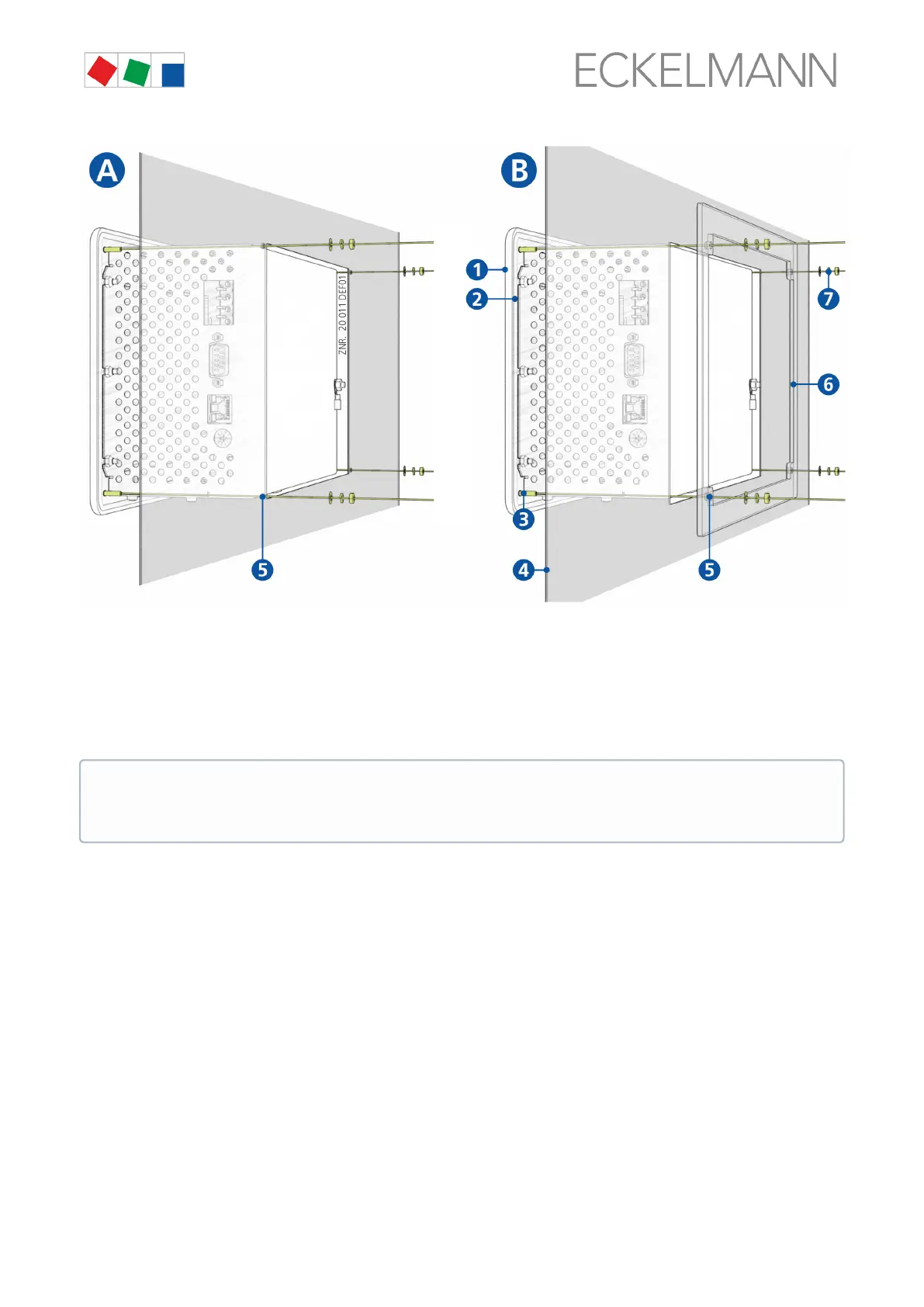
(1): Front panel
(2): Rubber seal
(3): 4 x stud bolt M3 x 10 mm
(4): Control panel with mounting cut-out
(5): 4 x drilled hole 4 mm
(6): 1 x mounting frame (part number KGLRAHMEN2, only required for variant B)
(7): 4 x M3: Washer / spring washer / nut
6.1.1 DIP Switches
Default settings of the DIP switches
The WDOG and BOOT DIP switches are located on the top side of the system centre housing and must be set
as follows for normal operation:
The technical specifications for the dimensions for the mounting cut-outs for the variants A and B are
shown in detail in chapter Control panel cut-out. For details about the wiring, see chapter System
centre and SIOX connection / terminal assignment.