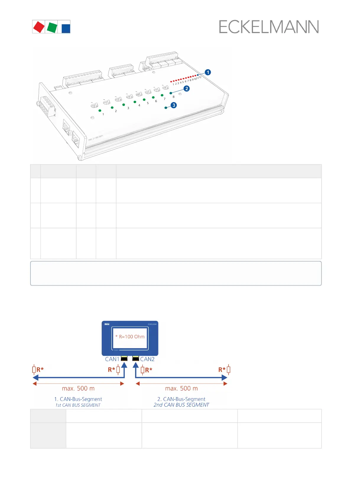
Function Colour LED Description
1 Digital
inputs
red LED1
..
LED12
On: Digital input is activated
ATTENTION DANGER TO LIFE: External voltage can be present at these terminals!
2 Relay
outputs
green LED1
..
LED8
On: Relay is activated
ATTENTION DANGER TO LIFE: External voltage can be present at these terminals!
3 Communicatio
n
green LED1
Flashing: Communication to the system centre is OK.
ON: Error - no communication! Check SIOX data cable if necessary.
OFF: Error - no communication! Check SIOX data cable and SIOX power supply cables if
necessary.
6.3 CAN bus - Connection of E*LDS Components
Depending on the expansion stage, up to two CAN bus segments can be connected to the system centre.
CAN1
(A) First CAN bus segment Standard for up to 127 CAN bus nodes --
CAN2 (B) Second CAN bus segment Only CI 4500 - System centre with repeater
function,
for up to a total of 127 CAN bus nodes on
both CAN bus segments
Menü 4-1-5 - Schnittstellen
For information about exact terminal assignment, see chapter System centre and SIOX connection /
terminal assignment.