Setting the CAN bus address is not required as the CAN bus addresses 111 and 127 are permanently assigned
tothesystemcentre.
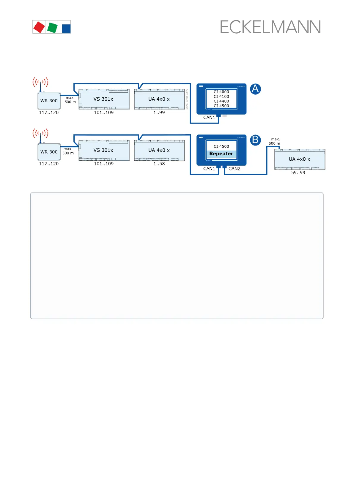
Example of possible CAN bus constellations:
For details about the connection, see chapter Terminal assignment of the CAN bus terminals.
ATTENTION
Damage to the installation and stock loss! If, when designing the system technology, the use of
pressure transmitters / temperature sensors at the refrigeration points of the 2nd CAN bus segment
(the one without pack controller) was dispensed with, we recommend in the unlikely event of a failure
of the system centre to reactivate it as quickly as possible!
Practical tip:
- Until the system centre is reactivated again, a CAN bus repeater can be used as a temporary
solution to exchange information (e.g. t
0
/ suction pressure) between the two CAN bus segments
CAN1 and CAN2.
-The evaporator input sensor R5.x should also be connected in the t
0
via CAN bus operating mode.
This results in improved emergency running characteristics in the event of failure of the CAN bus
transmission. In standalone operation (failure of the CAN bus and without local pressure transmitter)
the sensors R5.x must be connected, see operating manual of the EEV controllers!
Each CAN bus segment can have a maximum length of 500 m; the specified cable type is LiYCY (TP)
2 x 2 x 0.75 mm².ForfurtherinformationabouttheCANbus,seetheoperatingmanual“Basics and
General Safety and Connection Notes”.
 Loading...